— 23 —
KV-24FV12/25FV12/25FV12A/25FV12C
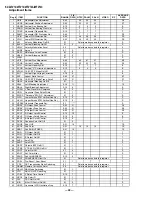
Reg #
ITEM
FUNCTION
RANGE
FIX
DATA
NTSC
PAL M
PAL N
VIDEO
RF
AVERAGE
DATA
64
VSS
Vertical Sync Slice Level
0,1
**
0
65
HSS
Horizontal Sync Slice Level
0,1
0
0
66
HMSK
0,1
0
0
67
VTMS
Select Signal VTIM Pin
0-3
0
0
68
CDMD
Vertical Count Down Mode Switching
0-3
3
***
0
69
AFC
AFC Loop Gain Switching
0-3
0
0
0
0
70
FIFR
Field Frequency
0-3
*
3
1
1
3
71
SBAL
Sub Balance
0-15
5
7
72
SBAS
Sub Bass
0-15
0
9
73
STRE
Sub Treble
0-15
3
9
74
BBEL
BBE Low
0-15
4
12
75
BBEH
BBE High
0-15
5
9
76
SRND
Surround
0,63
0
13
77
BBE
BBE On/Off
0,1
0
1
78
DISP
O.S.D Display Position
0-63
15
15
79
TROT
Tilt Correction
0-63
31
31
80
HCLW
Horizontal Count Lower Limit
0-127
16
16
81
HCHG
Horizontal Count High Limit
0-127
64
64
82
ABL0
0,1
4
1
83
ABL1
0-7
7
84
SYSC
Color System
0-7
0
6
85
VENH
Vertical Enhancement
0-7
0
4
86
CBPC
0,1
3
0
87
BYCF
0,1
0
0
88
KILC
0,1
0
89
LDOT
0,1
1
0
90
CORE
0,1
1
0
91
CHTR
0,1
0
92
CHPF
0,1
1
93
ENHO
0,1
0
94
ID0
0,255
25
See ID Map
95
ID1
0,255
3
See ID Map
96
ID2
0,255
91
See ID Map
97
ID3
0,255
2
See ID Map
98
ID4
0,255
233
See ID Map
99
ID5
0,255
17
See ID Map
100
ID6
0,255
0
See ID Map
* FIFR = 3 for NTSC models, FIFR=1 for Trinorma models
** VSS = 1 for US & CND, VSS=0 for Other
*** CDMD = 3 for US & CND, CDMD =0 for Other
**** KV-25FV12A/25FV12C =1; Others = 0
Palette mode controls this register
Palette mode controls this register
5-4. MB BOARD ADJUSTMENTS
H. Frequency (Free Run) Check
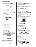
1. Input a TV mode (RF) with no signal.
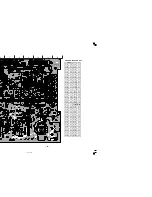
2. Connect a frequency counter to base of Q501
(TP-500 H. DRIVE) on the A Board.
3. Check H. Frequency for 15735 ± 200 Hz, and 15650 ± 200
Hz for PAL-N (KV-25FV12A ONLY.)
Notes:
No. 1–100 show the order that each adjustment mode may be selected while in service mode.
Data Range shows the range of possible settings for each adjustment mode.
Initial Data shows the standard settings for each adjustment mode.
Feature ID Map
V. Frequency (Free Run) Check
1. Select video 1 with no signal input.
2. Set the conditions for a standard setting.
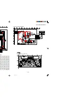
3. Connect the frequency counter to TP-502 (V OUT) or
CN501 pin
(V DY+) and ground on the A Board .
4. Check that V. Frequency shows 60 ± 4 Hz
for NTSC, 50 ± 4 Hz for PAL-N (KV-25FV12A ONLY).
Drive (RDRV)
1. Input a color-bar signal and set the level to 75%.
2. In Standard mode, set PICTURE to maximum and
COLOR to minimum.
3. Activate the Service Adjustment Mode.
SERVICE ID0 25
Destination
ID-0 ID-1 ID-2 ID-3 ID-4 ID-5 ID-6
KV-24FV12
(US)
89
19
239
50
137
19
0
KV-24FV12
(CND)
89
19
239
50
137
19
0
KV25FV12
(E)
17
19
255
2
233
19
0
KV25FV12C
(E)
17
19
255
2
233
19
0
KV25FV12A
(E)
23
19
255
2
233
19
128

