— 28 —
KV-32XBR200/KV-36XBR200
4. Connect an oscilloscope to CN351 pin
3
on A board.
5. Set to Service Mode and select 2COL and 2HUE with
and
.
6. Adjust with
and
for 2COL and 2HUE so that even
flat signal.
7. After adjust write 2HUE data 4 steps down.
8. Write into the memory by pressing
then
.
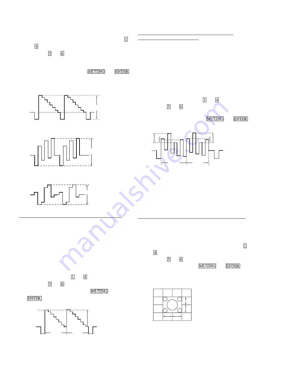
(75 ohms open level)
Y LEVEL (INPUT)
1.65Vp-p
B-Y LEVEL (INPUT)
1.05Vp-p
R-Y LEVEL (INPUT)
1.05Vp-p
P&P SUB CONTRAST ADJUSTMENT (MSCO, ISCO)
1. Input a 75% color-bar signal.
2. Set: VIDEO mode = STANDARD
PICTURE = 100%
COLOR = minimum
GON = 0 (OFF), BON = 0(OFF),
TRINITONE = medium.
3. Set P&P mode.
4. Connect an oscilloscope to CN1103 pin
4
of A board and GND.
5. Set to Service Mode and select MSCO (main window) and
ISCO (sub window) with
and
.
6. Adjust with
and
for the 1.75 ± 0.05Vp-p of level.
7. Write into the memory by pressing
then
.
1.75
±
0.05Vp-p
SUB
MAIN
P&P SUB COLOR, SUB HUE ADJUSTMENT
(MCOL, MSHU, ICOL, ISHU)
1. Input a 75% Color-bar signal.
2. Set: VIDEO mode = STANDARD
PICTURE = 100%
COLOR = 50%
HUE = 50%,
TRITONE = medium.
3. Set P&P mode.
4. Connect an oscilloscope to CN1103 pin
5
of A board and GND.
5. Set to Service Mode and select MCOL , MSHU (main window)
and ICOL, ISHU (sub window) with
and
.
6. Adjust with
and
.
7. After adjust write MSHU and ISHU data 1 step down.
8. Write into the memory by pressing
then
.
V1
V3
V4 V1’
V3’
V4’
SUB
MAIN
SUB COLOR
V1–V4= ±0.1V
V1’–V4’= ±0.1V
SUB HUE
V3–V2= ±0.1V
n
1
STEP DOWN
V3’–V2’= ±0.1V
n
1
STEP DOWN
P&P ACQUISITION ADJUSTMENT (MAHP, MAVP)
1. Input a Monoscope signal.
2. Set PICTURE = 100%.
3. Set P&P mode and set CHANNEL INDEX mode.
4. Set to Service Mode and select MAHP and MAVP with
and
.
5. Adjust with
and
for the best center (main window).
6. Write the memory by pressing
then
.
NEED TO ADJUST AFTER
GEOMETRIC ADJUST
A–B =
±
0.2 sg
C–D =
±
0.2 sg
A
B
C
D


