13
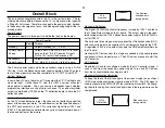
Convergence of the Three Beams
The good news is that the complex convergence signal is made in one
IC5513 and the signal is amplified in the second IC5515. The output
signal drives a convergence yoke inside the main horizontal and vertical
deflection yoke. The convergence stage affects the beams at the perim-
eter of the screen.
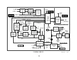
Dynamic Focus Correction
As a beam is deflected, the points of focus form a curve. The focus points
have to be moved to match the flat screen of the TV. A signal from DF
IC5511 modulates the DC focus voltage to prevent poor focus at the left
and right sides of the screen.
Video Processing
Standard Resolution Input – A standard resolution NTSC signal can be
selected from either tuner or any video input. However, this high resolu-
tion TV runs at a different horizontal frequency of 33.75kHz. To accept a
standard NTSC signal (480i) that runs at 15,734 Hz, the video signal is
improved and the horizontal sync more than doubled.
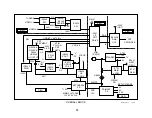
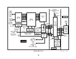
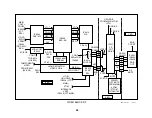
The Digital Reality Creation Circuit (IC3303) analyzes each pixel of a line
to add another line. Therefore the DRC circuit doubles the number of
video lines of a standard NTSC signal. The DRC also doubles the hori-
zontal sync frequency before passing the signal onto the MID circuit on
the same board.
The Multi Image Driver (MID) Circuit (IC3408) stores the lines and out-
puts the signal based on a new horizontal frequency that matches the TV.
At the higher frequency, the picture finishes before the scan. Blank lines
are added as filler by this MID stage before leaving the board.
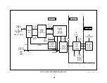
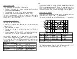
High Resolution Input - Video inputs 5 and 6 are for Y, Pr and Pb compo-
nent signals only. They can be standard (480i) or high resolution (480p or
1080i). The 480p signal is already high resolution at double the H freq so
it need not go through the DRC circuit. It is switched directly into the MID
circuit.
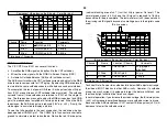
The high-resolution 1080i picture is at the same horizontal frequency as
the TV set (33.75kHz), so it does not go into the DRC or the MID circuit.
The 1080i signal is switched directly to the Y/C CRT Drive IC201 on the A
board.
Since the 1080i signal is a wide 16:9 ratio picture, it looks squeezed in on
a 4:3 aspect ratio picture tube. To make the picture look correct, the
vertical can be reduced using a “16:9 enhanced” menu command. Verti-
cal reduction can be automatically done if there is a code in the vertical
blanking area of the input signal called ID-1. This signal identifies the
aspect ratio of the picture.
Summary of Contents for KV-32XBR400
Page 1: ......
Page 5: ...1 NOTES ...
Page 12: ...8 NOTES ...
Page 14: ...10 NOTES ...
Page 83: ...APPENDIX ...

