55
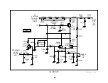
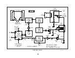
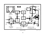
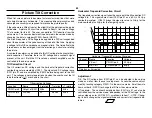
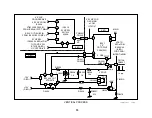
DF Switching Signals
Channel
Name
Location
Voltage
1
AFC-PLS
IC5511/pin 19
10Vp-p
2
SWO (Switch control)
IC5511/pin 14
0.3Vp-p (main)
3
Switch Drive signal
Q8016/Base
0.1Vp-p (main)
4
Final DF Drive Signal
Q8016/Collector
140Vp-p
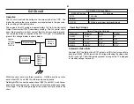
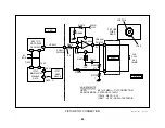
The purpose of “DF Protect” transistors Q8019 and Q8020 in the switch-
ing path is unknown as of this writing.
Adjustment
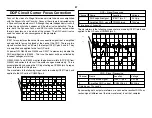
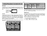
The manual focus adjustment is located on the flyback (the only control).
Input a crosshatch and adjust the focus control until you can see the scan-
ning lines in the picture.
Dynamic focus can be turned ON/OFF and phase adjusted (start loca-
tion) in the service mode. Data group #7 with the heading “2026” con-
tains two items related to dynamic focus:
Service Mode Category 2026
Item Name
Purpose
DFON
Data 0 = dynamic focus ON
Data 1 = dynamic focus OFF
DF
Positions IC5511/pin 14 switching pulses to change the
start of the dynamic focus points on the screen.
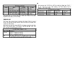
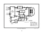
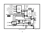
Service mode item “DFON” turns OFF the switching voltage from IC5511/
pin 14. This can be seen in the following chart that contains the DC
voltages of the output stage.
DF Output Stage Voltages
DFON data =
Q8018/C
T8002/pin 3
T8002/pin 1
0 (DF is On)
-14Vdc
89Vdc
91Vdc
1 (DF is Off)
0.3Vdc
0Vdc
0Vdc
Summary of Contents for KV-32XBR400
Page 1: ......
Page 5: ...1 NOTES ...
Page 12: ...8 NOTES ...
Page 14: ...10 NOTES ...
Page 83: ...APPENDIX ...

