65
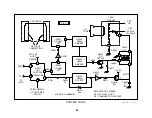
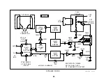
Straighten top
& bottom lines
using VPIN
adjustment
PM3394, FLUKE & PHILIPS
ch 2
ch 1
CH1! 200m V~ STOP
CH2!1.00 V~ MTB5.00ms L=2 ch1p
1
2
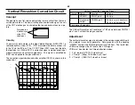
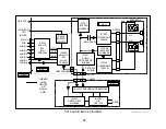
Vertical Pincushion Correction Circuit
Concept
The geometry on a flat screen picture tube is more critical than that on a
curved picture tube. This new circuit applies an electronic signal to a coil
at the CRT electron gun to straighten the top and bottom lines on a pic-
ture.
Circuitry
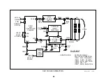
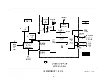
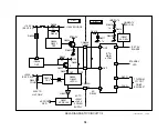
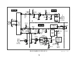
At power ON, data stored in the Non-Volatile Memory (NVM) IC707 is
retrieved by Main uCom IC701. IC701 distributes the data to various ICs
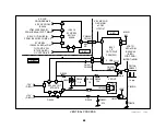
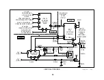
in the TV via the I2C bus. The Y/C CRT Drive IC201 is sent just the data
that pertains to it. Within IC201, a correction signal is made consisting of
mixed horizontal and vertical components. This signal is amplified by
IC5514 and applied to the pincushion coil.
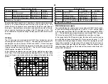
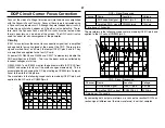
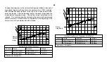
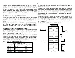
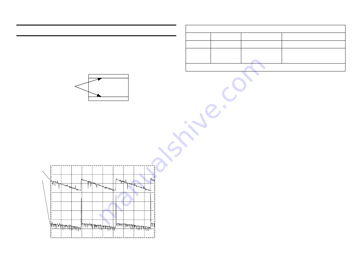
The correction signals before and after amplifier IC5514 is shown in this
scope shot.
Vertical Pincushion Correction Signal
Channel
Name
Location
Voltage
1
VSAWO
CN201/pin 6
0.3Vp-p
2
Pincushion
Output
CN5509/pin 2
0.5Vp-p = main waveform
3.5Vp-p including spike
Time base = 5msec/div.
The Vertical Pincushion coil resistance is 18.9 ohms between CN9102/
pins 1 and 2 without the plug connected.
Adjustment
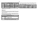
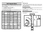
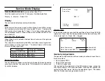
The vertical pincushion signal is adjusted in the service mode with the aid
of an external cross hatch generator. Data group #4 with the heading
“2150
D-1
” contains the VPIN adjustment in its fifth item. The fourth item
VCEN also changes the DC level of the VPIN signal.
VPIN must be adjusted in all three deflection modes:
1. Full - (normal NTSC) 4:3 signal input.
2. V Comp1 - (480p) 16:9 video 5 or 6 input.
3. V Comp2 - (1080i) 16:9 video 5 or 6 input.
Summary of Contents for KV-32XBR400
Page 1: ......
Page 5: ...1 NOTES ...
Page 12: ...8 NOTES ...
Page 14: ...10 NOTES ...
Page 83: ...APPENDIX ...


