67
c h 4
c h 3
c h 2
c h 1
c h 3 : d c = 2 6 .2 m V
c h 4 : d c = 1 6 3 m V
C H 1 !2 .0 0 V =
C H 2 !2 .0 0 V =
C H 3 !1 .0 0 V ~
C H 4 !2 .0 0 V = C H P M T B 5 .0 0 m s c h 1 -
1
2
3
4
T
Vertical Process
The vertical sync source selection on the B board is new, but the oscillator
and output stage is traditional.
Vertical Sync
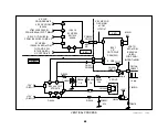
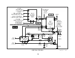
The vertical frequency is 60Hz but the sync is selected by IC4313 from
one of three sources:
1. MID circuit when Progressive scan is selected by the user (IC4313/
pin 13 input).
2. Main video input from input switch IC3048 when interlace scan is se-
lected (IC4313/pin 1 input).
3. Sub video input from sub picture switch IC3001 when this picture is
the only one selected (from the Twin mode). (IC4313/pin 2 input)
Switch IC4313 selects one input that outputs pin 14. The selection is
based upon control voltages from MID uCom IC3090 and the Main uCom
IC701 input IC4313/pin 9-11.
Vertical Oscillator
The vertical oscillator inside IC201 starts and outputs pins 52 and 53 when
Main 9V is applied to IC201/pins 55 and 61. Data need not be present for
vertical drive to output like other Y/C “Jungle” ICs.
Vertical Output
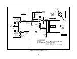
The vertical stage is traditional. The vertical oscillator signal is amplified
in IC5004 and used to drive the vertical deflection yoke.
To make sure the vertical stage is operational, a sample of the vertical
signal is returned to IC201/pin 35. If IC201 detects a loss of vertical pulses,
it blanks the picture. If the loss remains for two seconds, IC201 sends
data to Main uCom IC701 to shut down the set and store the vertical
failure code.
Vertical pulses from IC5004/pin 3 are sent to the MID uCom IC3090/pin
35 to identify the end of the scan for interlace/progressive scan timing.
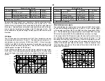
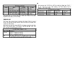
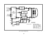
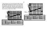
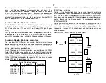
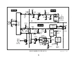
The waveforms of this stage show the basic operation from sync input
(ch1) through drive (ch 2) to feedback (ch 3 & 4).
Vertical Stage Waveforms
Channel
Name
Location
Voltage
1
Mid VS (sync)
CN003/pin B15
3Vp-p
2
V Drive +
CN5503/pin 4
1.8Vp-p
3
Protect signal
CN5505/pin 7
1Vp-p
0.8Vdc
4
Timing
CN5501/pin 1
3.5Vp-p
Time base =5msec/div.
Vertical Compression / 16:9 Enhancement
When a 16:9 video signal is input from video 5 or 6, the aspect ratio is
incorrect for this 4:3 TV screen and the picture will appear too tall. The
vertical is compressed slightly to maintain the correct aspect ratio. The
user chooses this compression from the menu. In the setup menu under
16:9 enhancement, he can choose AUTO or ON. In AUTO, the MID
circuit on the D board detects the higher horizontal frequency associated
with a 1080i 16:9 picture and reduces the vertical sweep. A 480p signal
can be in either aspect ratio. Therefore the user must manually select ON
for the vertical compression.
Summary of Contents for KV-32XBR400
Page 1: ......
Page 5: ...1 NOTES ...
Page 12: ...8 NOTES ...
Page 14: ...10 NOTES ...
Page 83: ...APPENDIX ...

