69
P M 3 3 9 4 , F L U K E & P H IL IP S
c h 2
c h 1
c h 2 : p k p k = 1 .5 5 V
c h 2 : fre q = 6 0 .0 H z
C H 1 !2 .0 0 V =
C H 2 ! 5 0 0 m V ~ M T B 2 .0 0 m s - 0 .9 0 d v c h 1 +
1
2
T
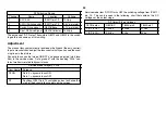
Ramp
Irregularity
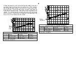
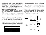
To keep the information in the vertical blanking area hidden in the vertical
area above the picture, the vertical drive waveform from IC201 is altered.
After the electron beam retraces to the top of the screen, normal down-
ward scan begins. After the blanking interval, the beam drops down the
screen before resuming sweep. The vertical ramp’s amplitude is also
reduced. This can be seen when comparing the normal and compressed
vertical waveform. Notice there is an irregularity at the beginning of the
vertical ramp in the compressed vertical mode.
PM3394, FLUKE & PHILIPS
ch2
ch1
ch2: pkpk= 1.78 V
ch2: freq= 122 Hz
CH1!2.00 V=
CH2! 500mV~ MTB2.00ms- 0.90dv ch1+
1
2
T
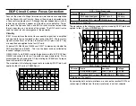
Normal
vertical
ramp
Vertical Drive Signal - Normal
Channel
Name
Location
Voltage
1
MID VS (sync)
CN3205/pin C15
3.5Vp-p
2
V Drive (osc)
CN5503/pin 4
1.5Vp-p
Time base = 2msec/div.
Vertical Drive Signal - Reduced (16:9 Mode)
Channel
Name
Location
Voltage
1
MID VS (sync)
CN3205/pin C15
3.5Vp-p
2
V Drive (osc)
CN5503/pin 4
1.3Vp-p
Time base = 2msec/div.
Summary of Contents for KV-32XBR400
Page 1: ......
Page 5: ...1 NOTES ...
Page 12: ...8 NOTES ...
Page 14: ...10 NOTES ...
Page 83: ...APPENDIX ...

