77
CN6505 CN6006
CN6504 CN702
CN6506 CN703
CN5503 CN201
CN5505 CN203
CN5501 CN706
10
1
10
1
11
1
10
1
8
1
8
1
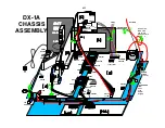
Bridge Connectors
6 1
CN6501
D
Board
6
1
A
Board
CN6005
Hot
Ground
IC
60
07
IC6007
Back of TV
O
I O G n/c
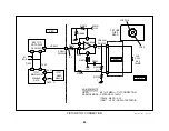
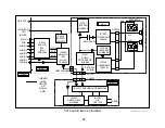
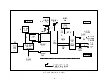
Then use your scope to examine the signal to the cathode. Go to CN9001/
pins 1, 3 and 5 to see if there is a signal coming into the C board. Next
check the signal at the CRT cathodes. If they are present, check the IK
signal from CN9001/pin 8 of the C board. You should see three pulses
and be able to change the level of the signal with the G2 control. If you
get about 1Vp-p pulses at pin 8, this is the normal output from the CRT/C
board so the problem is on the A board about IC201.
Shutdown - Standby light blinks six times
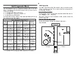
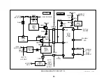
Circuit - IC701/pin 43 monitors the Set 5V supply from the power supply
on the A board. This voltage feeds almost all the boards. A short on the
Set 5V line will cause IC701 to shut off the AC relay (IC701/pin 69 goes
LOW).
Testing - At power ON, measure the “Set 5V” at regulator IC6007/Output
on the A board. The trip voltage is 3.7Vdc. If this voltage remains low at
power ON, unplug the B board within the A board and power ON again.
Shutdown - Standby light blinks seven times
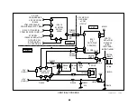
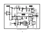
There are two +135V OCP monitoring circuits. The first circuit will cause
the Standby light to blink two times and the second will cause the light to
blink seven times. Both sensing and output circuits are on the D board,
but the indicating circuit is on the A board.
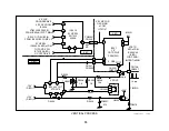
Circuit - The second OCP circuit monitors the current through the PWM
Output (Q5001-3) that supplies B+ voltage to the H. Output transistor
Q5030. When there is excessive current drawn by the Horizontal Output
stage, Q5018 turns OFF, permitting IC201/pin 34 to rise to a threshold of
1.2Vdc. IC201 blanks the picture to prevent a CRT line burn and sends
data to IC701/pin 30 to shut down the TV.
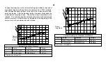
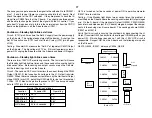
Normal Operating Voltages
Location
At power ON
Operating
IC5007/pin 8
0.07V
0V
IC5007/pin 9
3V
3V
IC5007/pin 1
2.6V
2.6V
Q214/base
5V for 5 seconds
0V
Q214 is turned on for five seconds at power ON to permit comparator
IC5007 time to stabilize.
Testing - If the Standby light blinks two or seven times, the problem is
most likely on the D board where the sensing and Horizontal Output stages
are. On the D board, if the Horizontal Output (Q5030), PWM (Q5003)
transistors, and video output ICs (C board) are good, suspect the compo-
nents in the sensing circuit (same board). The sensing parts are Q5004,
IC5007 and Q5018.
Verify that this circuit is causing the shutdown by disconnecting the H.
Output Transistor Q5030 and monitor the voltage at CN5505/pin 8 as you
power ON. If this voltage rises above 1 volt, this +135V OCP circuit is
responsible. Suspect Q214 on the A board and the following main parts
on the D board:
R5013, Q5004, IC5007, delay cap C5006, Q5018.
Summary of Contents for KV-32XBR400
Page 1: ......
Page 5: ...1 NOTES ...
Page 12: ...8 NOTES ...
Page 14: ...10 NOTES ...
Page 83: ...APPENDIX ...

