ix
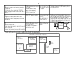
B
Remove 4 screws from the rear panel and
fold it down.
Pry the locks from connectors CN3202/3
while wiggling the B board away form the A
board.
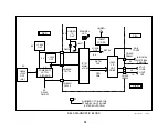
Video processing and audio
switching.
Closed caption/V Chip
DRC for line doubling
MID for twin pictures
Loss of video, Y or C.
Loss of sync to main
or sub pix.
Transplant memory IC3089 containing Twin
picture parameters.
C
Wiggle the C board off the CRT neck.
Unsolder the CRT socket and install on the
new board.
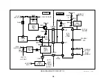
RGB CRT signal amplifiers
Dark screen (adjust
G2 first)
Stby light blinks 5
times & repeats.
Adj Screen control according to the service
manual: Reduce vertical size to see IK line at
the top. Blank pix in the service mode by
changing CXA2150P-2/ALBLK data from 0 to
1. Adjust screen control so the IK line is just
invisible in a dark room.
W
Remove the C board.
Mark the pix tube neck to reinstall the new W
board assembly.
Loosen the clamp and remove the assembly.
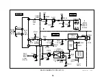
Velocity Modulation circuit
to improve detail
Top/bottom Pincushion &
corner focus coils
White outline along
object.
* Refer to the service manual s section 5 for the list of adjustments.
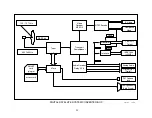
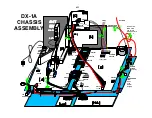
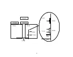
W board
clamp
G1
Pix
tube
Dynamic
Convergence
Secondary
Power Supply
HV Regulator
FBT
Horizontal
Deflection
Vertical
Primary
Power Supply
S Bd
(audio)
B board
(video)
Stby
Circuit
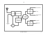
HA/HB boards - Front panel remote & buttons
Summary of Contents for KV-32XBR400
Page 1: ......
Page 5: ...1 NOTES ...
Page 12: ...8 NOTES ...
Page 14: ...10 NOTES ...
Page 83: ...APPENDIX ...

