11
SETU
P
Set
up
S
E
TU
P
SETU
P
S
E
TU
P
SETU
P
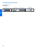
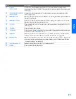
Item
Description
1
S VIDEO
VIDEO 2 INPUT
Connects to the S VIDEO OUT jack on your camcorder or other video
equipment that has S VIDEO. Provides better picture quality than composite
video (
2
).
2
VIDEO/L(MONO)-AUDIO-R
VIDEO 2 INPUT
Connects to the composite A/V output jacks on your camcorder or other
video equipment.
3
MEMORY STICK
Memory Stick insertion slot. For details, see “Using the Memory Stick Picture
Viewer” on page 54.
4
MEMORY STICK LED
When lit, indicates that the Memory Stick is being read. (Do not remove the
Memory Stick when the indicator is lit.)
5
TV/VIDEO
Press repeatedly to cycle through the video equipment connected to the TV’s
video inputs.
6
-
Press to adjust the volume.
7
-
Press to scan through channels. To scan quickly through channels, press and
hold down either
CHANNEL
button.
8
TIMER LED
When lit, indicates one of the timers is set. When the timer is set, this LED
will remain lit even if the TV is turned off. For details, see page 77.
9
STAND BY LED
Blinks when the TV is turned on, then shuts off when the picture is displayed.
If the LED blinks continuously, this may indicate the TV needs service (see
“Contacting Sony” on page 82).
0
Infrared Receiver (IR)
Receives IR signals from the TV’s remote control.
qa
POWER
Press to turn on and off the TV.
34XBR.book Page 11 Wednesday, April 24, 2002 3:15 PM
Summary of Contents for KV-34XBR800
Page 5: ......
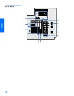
Page 13: ...12 SETUP SETUP SETUP SETUP Setup SETUP Rear Panel q 2 3 4 5 9 8 7 6 1 ...
Page 79: ......
Page 91: ......


