background image

Summary of Contents for KV-HR36M31

Page 1: ...HCSD ID 079663 MODEL COli lidANDEP m CHASSIS NO MGDE L COMMANDER m CHASSIS NO m HR36M31 RM 1007 o c scc MI A A 1 I TRINITRONa COLORTV ...

Page 2: ... 5W I3D Woofer w 1 Number of terminal Q Video b Audio 53 SVideo D Component Video f J G B WHD VD Video D c Center Speaker 2 Headphones Picture tube Tube size cm measured diagonally Screen size cm measured diagonally Dimensions wlhld mm Mass kg Input 4 Output Phono jacks I Vp p 75 ohms Input 6 Output 1 Phono jacks 500 mVrms Input 2 Y 1 Vp p 75 ohms unbalanced sync negative C 0 286 Vp p 75 ohms Inpu...

Page 3: ...Y CONNECTED TO THE AC POWER LINE SAFETY RELATED COMPONENT WARNING COMPONENTS IDENTIFIED BY SHADING AND MARK A ON THE SCHEMATIC DIAGRAMS EXPLODED VIEWS AND IN THE PARTS LIST ARE CRITICAL TO SAFE OPERATION REPLACE THESECOMPONENTS WITH SONY PARTS WHOSE PART NUM BERS APPEAR AS SHOWN IN THlS MANUAL OR IN SUPPLE MENTS PUBLISHED BY SONY CIRCUIT ADJUSTMENTS THAT ARE CRITICALTO SAFEOPERATION ARE IDENTIFIED...

Page 4: ... BOARD 56 6 DIAGRAMS 6 1 BLOCK DIAGRAM 1 57 BLOCK DIAGR4M 2 59 BLOCK DIAGR4M 3 61 BLOCK DIAGRtLM 4 63 BLOCK DIAGRAM 5 65 BLOCK DIAGFUM 6 67 BLOCK DIAGRAM 7 69 BLOCK DIAGRAM i8 71 BLOCK DIAGRAM 9 73 BLOCK DIAGRAM 10 74 BLOCK DIAGRAM 11 75 6 2 CIRCUIT BOARDS LOCATIOS 76 6 3 PKLNTED WIRLWG BOARDS AND SCHELMA TIC DI 4GRAMS 76 6 4 SEMTCONDGCTORS 173 7 EXPLODEDVIEWS 7 1 CHASSIS SECTION 175 4 SET UP ADJU...

Page 5: ...curred 1Nunrber tmes Diagnosis Item 1 indicator b M s Probable Cause Location I Detected SJmptoms 1 B overcurrent IOCP 1 2 times 1 78001 FBTl Rare sllort circuit etc D board entered standby mode 1 Q5001 H OUT Q5006 iD board Relay is off when the power I turns on 1 B loau open iD board R6570O p e C p 1 B overvoltage IOVP 3 times I PH8003 control system malfunction L2603 1 Has entered standby mode O...

Page 6: ...or details refer to the item 1 6 4 Self diagnosis screen displays In cases of malfunctions where it is not possible to determine the symptom such as when the power goes off occasionally or when thc screen disappears occasionally there is a screen display on whether the malfunction occurred or not in the past and whether the detection circuit operated or not in order to allow confirmation Screen Di...

Page 7: ...r off Set to the standby mode z l lo_l 1 x 1 r 1 Service Mode 3 Channel Test reset Factory presel condition Method of Ending Self Diagnosis Screen When ending the self diagnosis screen completely turn the powcr switch OFF on the remote commander or the main unit AUDIO PROT FROM A BOARD LOW B ERR FROM A BOARD 1 HV PROT FROM D BOARD 1 I 1 MJ BOARD ovP FROM A D BOARD MAIN MICRO AC RLY MICRO TO A BOAR...

Page 8: ...the return data Bit1 HNG from CX42170 is 1 while 2 seconds turn AC RELAY low P OFF m d make STANDBY LED blinks seven times Obsenies the watch dock timer BUS COMMLWIC iTION ERROR DET bus communication If errors are detected counts up and reform the bus communication and displays the number of time No LED blinking In case of P i n85 of ICSOl AUDIO PROT DET turns high 60msec twice at a time makes AC ...

Page 9: ...Y 2 3 SERVICE POSITION Four screws BVTP 4x16 I 1 bottom v C L Three screws BVTP 4x16 PJ q b Screw i BVTP 4x16 A support dThree screws i BVTP 4x16 2 2 CHASSIS ASSEMBLY 2 4 SPEAKER BOX ASSEMBLY Two screws TWHTP 4x25 4Connector Speaker assembly box ...

Page 10: ...T AND UG BOARDS Two connectors Screw i T board 2 6 BM AND MG BOARDS 2 7 A BOARD BM board with MS2 board Connectors CN6100 CN6101 CN6006 CN6010 9 0 Three screws BVTP 3x12 ...

Page 11: ...ctors Three screws BVTP 3x12 L L C N 3 8 0 9 SF board 2 10 H3 H4 H5 AND HMG BOARDS Connectors Cnnn rtnrs CN1OO1 Connectors to 1003 h CN9302 9303 CN7204 Screw Connectors OScrew BVTP 3x 8 O Screw H4 board I RVTP 3x1 Connectors CN1054 1 H5 board ...

Page 12: ...2 11 HARNESS ARRANGEMENT CN6006 CQIL NA ROTATION ...

Page 13: ...ed by the arrow When one side of the rubber cap is separated from the anode button the anode cap can be removed by turning up the rubber cap and pulling it up in the direction of the arrow O a HOW TO HANDLE AN ANODE CAP Do not damage the surface of anode caps with sharp shaped objects Do not press the rubber too hard so as not to damage the inside of anode cap A metal fitting called the shatter ho...

Page 14: ...ving the anode short circuit the anode of the picture tube and the anode cap to the metal chassis CRT shield or carbon paint on the CRT Speaker box assembly coil 9Chassis assembly 1 C w Neck assembly Anode cap Crown washer TP ...

Page 15: ...e adjustment item 5 Press or on the Remote Commander to change the data 6 Press or aon the Remote Commander to select the Adjustment item up Adjustment item down category 7 If you want to recover thelatest valuespress then TR IP to read the memory 8 Press iLVB3Gthen to write into memory 9 Turn power off Note Press then on h e Remote Commanderto initialize or turn set off and on to exit 3 3 MEMORY ...

Page 16: ...3 5 SERVICE MODE LIST Standards l RF CV I Y C CO fP So Same Standards 2 Standards 3 ...

Page 17: ...Standards 1 a r i c v I r 1 r n w RGH i IS I Twin ...

Page 18: ...Standards 3 ...

Page 19: ...t SHFO 1 1 1 1 1 1 1 1 I 1 l 1 1 1 1 8 1 PROV 3 3 3 3 3 v 3 3 1 9 FlLV 0 0 0 0 0 0 1 0 0 1 1 0 0 0 0 in i n x i n n n n n n l n n n n n Functionality NO xame n I SYSLf I 0 3 I 1 Rarige Standards ...

Page 20: ...Standards 2 10 IT LV 0 0 0 J C 0 0 0 0 0 0 11 12 13 LTMD CTL V l i D E i 0 0 rj 0 I 0 0 1 1 0 1 0 4 1 4 I 0 4 I 3 8 3 X I 0 24 1 0 24 1 0 16 I 0 16 I 3 16 I 0 16 ...

Page 21: ...7 5 U 4 1 0 0 1 0 0 1 0 I n o l n n 1 I n l n n n ...

Page 22: ......

Page 23: ...for 41s mode only Standards I ...

Page 24: ...Standards 3 ...

Page 25: ...tU CZI i 7 r Standards 10 AIHC CD M CDlf3 CDM3 Standttrds 11 No 1 V m c I RF 1 LV I YClOther 39 1 SLPF I 0 1 0 1 0 CVNC 0 0 ri Standards 12 Other 0 0 I 0 2 0 0 0 i 0 Standards 13 No Name I SD 1 Other 12 CDLP 1 1 0 13 1 ROM2 I 0 1 0 No Standards 14 1 l N C O M I 0 0 1 0 1 I 0 1 0 Name O H Z I 5nwz Rt 1BS1CVfl C Other 1 RF I CV YC Other ...

Page 26: ...Standards l5 Oiily At Auw Calor SysIem Mode Only At Auto Color System Mod Staudards I6 ...

Page 27: ...COMB Functionabt Range Standards 35 DTCR 1 1 36 DZFC 3 3 3 3 37 D2F 9 4 S 8 41 C V F L 3 1 o 1 3 1 0 42 1 HlDD 0 1 I I 0 1 49 50 52 53 MKMM GHLT MNSW bWYE 0 0 3 0 0 0 0 3 0 0 0 0 0 1 0 0 0 ...

Page 28: ...Standards I Standards 1 Stmdards 2 ...

Page 29: ...MCY ...

Page 30: ... 3 1 VLIX j 1 vsco 4 1 VCEN 5 VPIX 6 1 NSCO 7 I m Z 8 1 ZOOM 9 SW Standards 3 Ranv 0 63 0 63 13 o ij 3 b3 0 7 1 10 I 1 13 14 Standard S Sr w d udi 24 I I 3 1 31 3 SPT SCRL CVLV LVLS VPSO Standards 6 0 63 1 3 i 0 31 15 0 1 3 0 1 3 67 1 53 0 15 0 15 0 15 5 5 I 5 7 ...

Page 31: ...20 1 UCPO I JIt 5 1 22 V4OC 1 0 7 1 I 23 i HIHS I 0 31 1 6 Standards 2 Standards 4 Standards 5 ...

Page 32: ...Standards 1 Standards Standards 5 ...

Page 33: ...MID I Standards I No Single 1 Other ODYCDI 2 2 So ISin e Norm 1 TwiwFrecz 1 IS 1 Index 1 DYSD I 1 1 1 1 1 1 0 Standards 3 ...

Page 34: ...WD Standards I Standards I Standards 2 VSW CRNR Standards 1 ...

Page 35: ...RNR c nnrtnmIs I ...

Page 36: ...Standard I ...

Page 37: ...SNNR Standards 1 N o N a m t I A 1 B 1 C I D 1 E 1 F 1 G 3 1 WSLII 1 5 1 20 1 45 1 63 1 7 5 1 110 1 127 Standards 2 OFSL SLOF FRU 0 3 LL IS L i i 1 RER UDEV Standards 1 ...

Page 38: ...Standards 1 ...

Page 39: ...Standards 1 Standards 4 ...

Page 40: ...11 12 Funcrionaiiy Rmge 5 O i 0 15 1 0 1 15 1 0 31 3 0 31 Yo I 1 3 1 j 7 7 S 9 is 11 TC1 Tc2 TC7 V D l VD WD3 TO4 Y L T l Y i 3 3 YLV3 11s CSPK Stanfiards 0 5 i 4 16 18 I Same T I 2 1 T i 2 77 3 VIDl VID VID vma I Y W YCi ATSC SECM 0 1 5 5 I5 O 15 i j 5 0 15 0 15 I5 t15 0 15 1 I5 0 31 I 0 1 1 17 ...

Page 41: ...andard 1 HI F ne 1 Personai L M L V 2 2 j 1 3 PFID Stxi 0 1 1 l 0 1 0 3 1 1 3 1 0 PFOP Range 0 1 I 0 I 0 255 0 755 0 1 0 3 0 1 0 3 0 1 0 3 0 1 l o 0 3 0 3 0 1 l unctionality 0 1 2 3 4 5 6 8 9 10 11 12 13 14 7 MFVR ISEl ORES ONCT W T F T H FSEL CDLY LMrl LMLV LMSL W L Y W P R W L L CKCT ...

Page 42: ...KV HW36M31 RM 1007 OSD Standards 1 MSP ...

Page 43: ...PIC Standards 1 Slmdards 2 Standards I ...

Page 44: ...Standards 1 ...

Page 45: ...Functionaiiq No Name 19 1 SIG 20 1 NSIG Signa Detect RF 1 Video 0 5 0 20 ...

Page 46: ...SRY ...

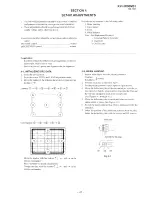
Page 47: ...adjustment mode 3 Move the marker in the order as shown in the figure and set its data to 0 Convergence 4 4 Move the marker with the buttons 7 I and on the remote commander Press ENTER to decide the position Change the data with the buttons 1 1 and on the remote commander 4 2 BEAM LANDING 1 Input a white signal with the pattern generator Contrast norm Brightness 2 Position neck assy as shown in Fi...

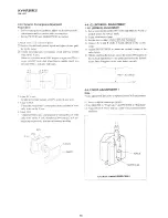
Page 48: ...hat the red green and blue dots are on top of each other at the center of the screen 2 hloving vertically adjust the V STAT magnet so that the red green and blue dots are on top of each other at the center of the screen 3 If the H STAT variable resistor cannot bring the red green and blue dots together at the center of the screen adjust the horizontal convergence with the H ST ATvariable resistor ...

Page 49: ...hatch signal and adjust PICTURE to MN and BRIGHTNESS to STANDAW 2 Adjust the Y separation axis correction magnet on the neck assembly so that the horizontal Lines at the top and bottom of the screen are straight Blue Neck assy b 4 1 r Cl I L p L J Red L 4 VM board Red Neck assy 4 3 L A Blue VM board Note 1 The Red and Biue magnets should be equally far from the horizontal center line 2 Do not sepa...

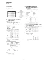
Page 50: ...d B of the C board cathode to the oscillo scope 5 Adjust BRIGHTNESS to obtain the cathode voltage to the value below 6 Whilst watching the picture adjust the screen VR located on the flyback transformer to the point just before the flyback return lines disappear to the point before cut off 170V 0 5 VDC I L 0 v 4 5 FOCUS ADJUSTMENT 1 Note 2 Adjust XCV core Focus adjustment should be completed befor...

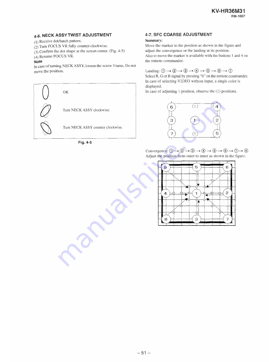
Page 51: ...MENT Summary Move the marker to the position as shown in the figure and adjust the convergence or the landing at its position Also to move the marker is available with the buttons 1 and4 on the remote commander an ding a a Select R G or B signal by pressing 6 on the remote conlmander In case of selecting VIDEO without input a single color is displayed In case of adjusting 1 position observe the 1 ...

Page 52: ... red gTeen or blue press 6 Xote In case of receiving TV signal a single color is mixed to the TV signal It is easy to adjust in VIDEO 1 to 3 without input because only a single color is displayed 2 Landing adjustment Adjust with the remote commander and to reduce the lack of uniformity on upper and lower side on the screen After adjustment press ENTER Then it becomes to moving marker mode and the ...

Page 53: ...Marker position to center it cannot be adjusting on the outside of the marker 4 8 SFC FINE ADJUSTMENT Landing Left 11points right 11 points SelectR G or B signal by pressing 6 on the remote commander In case of selecting VIDEO without input a single color is displayed Convergence Move the marker from the center to outer spirally Only the center data is within 15 Fine mode o Landing J 4 8 1 Landing...

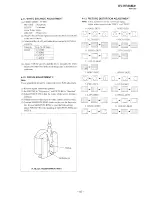
Page 54: ...V ___j Reg No Name 4 10 P P SUB HUE AND SUB COLOR ADJUSTMENT VIDEO NTPC PAL 1 Receive the signal TV terminal sub Color bar whte 75 No setup Standards 1 1 0 0 1 100 1 IMCp 2 I R 5 Connect anoscilloscope between pin B DRV of CN9001 C board connecter and ground 6 Adjust the item as shown below to have VBl 5 VB4 and VB2 5VR in the waveform levels VZDEO terminal main Color bar while 75 No setup 2 V D E...

Page 55: ...STMENT 2 Note Focus adjustment should be completed before W R adjustment BDRV GCCT BCCT 1 Receive digital monoscope pattern 2 Set DRC YE to Progessive and PICTURE to Standard 3 Adjust FOCUS VR so that the center of the screen becomes justfocus 1 Change the receivin signal to white pattern and blue back 5 C o d m MAGENTARING shouldnot be over the limit sam ple In case Mt GEhTA RllVG is over the lim...

Page 56: ...5 4 IK PROTECTOR CIRCUIT CHECK D BOARD When replacing the following components marked with on the schematic diagram always check IKprotector circuit D8004 IC8001 28007 Q8008 R8027 R8029 R8030 R8031 R8035 R8037 R8038 R8039 R8040 R8041 R8043 D board 1 Unsolder T800 1 FBT Pin 1and connect a DCcurrent meter between Pin i and the pattern 7 Short circuit CYOl5 3 Turn power on feed the dot signal and set...

Reviews: