– 31 –
KV -PF21K70
RM-960
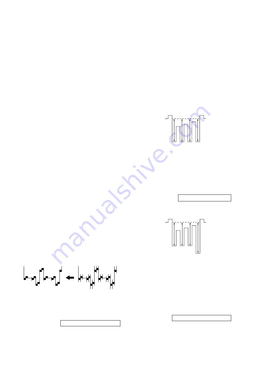
SUB HUE ADJUSTMENT
1.
Select Video
1.
2.
Input a NTSC color-bar
, video into V
ideo 1.
3.
Set the following condition:
PICTURE 100%, BRIGHTNESS 50%, COLOR
50%
4.
Connect an oscilloscope to pin
1
(B OUT) of CN305, A board.
5.
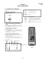
Select SAJ 1 ‘SHU’ with
1
and
4
of the commander by set-
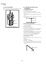
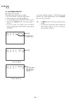
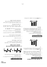
ting to Service Mode and adjust to VB1=VB2=VB3=VB4 with
3
and
6
.
4-3.
PICTURE QU
ALITY ADJUSTMENTS
SUB COLOR ADJUSTMENT
1.
Input a PAL color
-bar.
2.
Set to the following condition:
PICTURE 100%, BRIGHTNESS 50%, COLOR 50%
3.
Connect an oscilloscope to pin
1
(B OUT) of CN30
5, A board.
4.
Set to Service Mode and select SAJ 3 ‘SCL’ with
1
and
4
of
the commander then adjust to VB2=VB3=VB4 with
3
and
6
.
5.
Press
[MUTING]
→
-
of the commander to write the data.
6.
Adjust SAJ 3 ‘SCL’ as step 2 to 5 when recei
ving NTSC color-
bar.
6.
Press
[MUTING]
→
-
of the commander to write the data.
BELL FILTER ADJUSTMENT
1.
Input SECAM color-bar signal.
2.
Connect the dual-trace oscilloscope to the pin
9
(R-Y) of
CN303 (not mounted).
3.
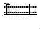
Adjust SERVICE MODE, ITEMS ‘SBF’
as shown belo
w.
4-4.
A BOARD ADJUSTMENT AFTER IC003
(MEMORY) REPLA
CEMENT
When replacing IC003 (MEMORY), be sure to change IC001
(µ-COM) to the following ne
w IC at the same time.
IC001 (µ-COM) : CXP86461-628S
1.
Enter to Service Mode.
2.
Press commander buttons
5
and
-
(Data Initialize), and
2
and
-
(Data Copy) to initialize the data.
3.
Call each item number and check if the respectiv
e screen sho
ws
the normal picture.
In cases where items are not well adjusted, rectify the items
with fine adjustment.
Write the data per each item number (
[MUTING]
+
-
).
4.
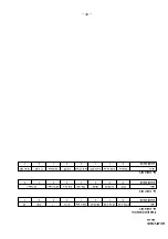
Select item numbers “OPB0” (OP1), “OPB1” (OP2) and
“OPB2” (OP3) and respectiv
ely set the bit per model with
command buttons
3
and
6
.
5.
Press commander buttons
8
and
-
(Test Normal) to return
to the data that was set on the shipment from the f
actory.
(This will also cancel Service Mode.)
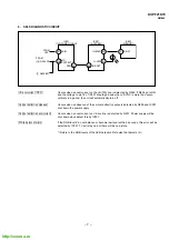
VB1
VB2
VB3
VB4
VB2 = VB3 = VB4
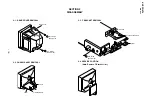
VB1
VB2
VB3
VB4
VB1 = VB2 = VB3 = VB4

