9
6. Service Mode
Service Status See Figure 6-9. This section displays the status of the input signal, and TV
condition.
Signal/sync - Format, freq, and sync polarity of the input signal.
Power Supply – Low voltage output of the power supply in voltage DC.
Fan & Temp - The fan voltage and power supply temperature. Within this category
is a No Ack Dev - Points to an IC that is not communicating with the Main Micro
using a 4-digit defect code number. See No Acknowledge Device table 6-2.
Warning Status – Shows completion of communications from the Main Micro (B
board) to memory IC and to 15 others.
Operation Time – Elapse TV ON time.
Software & PLD version – Software in Main micro and Panel Micro.
Table 6–2 - Service Mode - Service Status under Fan and Temp, No Acknowledge Device
Defect Code
Suspected IC
Defect Code
Suspected IC
0001
Audio Processor (A board)
0002
Audio Switch (Q board)
0004
AV Switch IC (U board)
0008
V Chip (Q board)
0010
3D Comb filter IC (B board)
0020
Color Decoder (B board)
0040
Plasma Panel (PDP)
0080
Tuner (TU board)
0100
Auto Wide IC (B board)
0200
A/D Converter (B board)
0400
EPROM (M board)
0800
System IC (B board)
1000
V Chip (Q board)
2000
PLD (B board)
4000
Real Time Clock IC (B board)
8000
Scan Converter (B board)
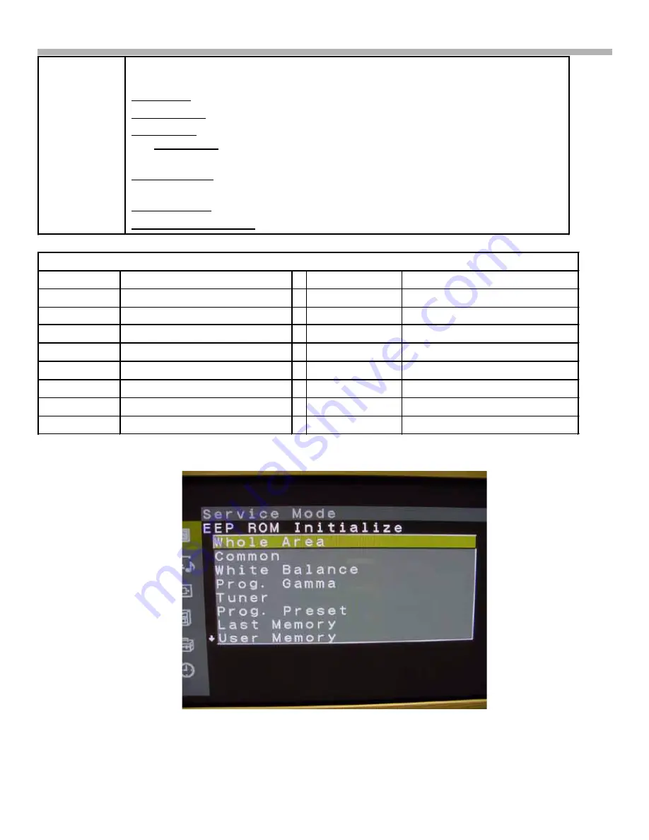
Figure 6-3 Service Mode - EEP ROM Initialize


