background image

LCD Monitor 

lnstructions for Use 

Before operating the unit, please read this manual thoroughly 

and retain it for future reference. 

LMD-2735MD 
LMD-2435MD 

CE: 

2016 Sony Corporation 

�  4-584-947-14(1) 

2020-02 

Summary of Contents for LMD-2435MD

Page 1: ...LCD Monitor lnstructions for Use Before operating the unit please read this manual thoroughly and retain it for future reference LMD 2735MD LMD 2435MD CE 0 2016 Sony Corporation 4 584 947 14 1 2020 02 ...

Page 2: ...e ME equipment where it is difficult to unplug the power plug If a fault should occur during operation of the unit operate the disconnect device to switch the power supply off or disconnect the power plug Symbols on the product cm Safety sign Follow the warnings in the instructions for use for parts of the unit on wbich this symbol appears NOTE Background color Blue Symbol White Consult the instru...

Page 3: ... This unit has been certified according to Standard CAN CSA C22 2 No 60601 1 lmportant safeguards and notices for use in the medical environments 1 All devices connected to the unit must be certi fied or compliant according to IEC 60601 1 IEC 60950 1 and IEC 60065 standards and other IEC ISO standards applicable to the devices 2 Furthermore the system as a whole must comply with IEC 60601 1 standa...

Page 4: ...tion of replacement parts sold by Sony Corporation may result in increased emissions or decreased immunity of the LMD 2735MD 2435MD Guidance and manufacturer s declaration electromagnetic emissions Tue LMD 2735MD 2435MD is intended for use in tbe electromagnetic environment specified below Tue customer or the user of tbe LMD 2735MD 2435MD should assure that it is used in such an environment Emissi...

Page 5: ...ntial typical commercial or hospital environment mode IEC 61000 4 5 2kV line s to 2kV common earth mode Voltage dips 0 UT 0 UT Not applicable Mains power quality should be that of a short 100 dip in 100 dip in typical cornmercial or hospital environment interruptions UT UT If the user of the LMD 2735MD 2435MD and voltage for 0 5 1 cycles for 0 5 1 cycles requires continued operation during power v...

Page 6: ...d separation distance calculated from tbe equation appliance to tbe frequency of the transmitter Recommended separation distance IEC 60601 1 2 2007 d 1 2 P 80 MHz to 800 MHz d 2 3 P 800 MHz to 2 5 GHz IEC 60601 1 2 2014 d 2 0 P 80 MHz to 2 7 GHz Where P is the maximum output power rating of the transmitter in watts W according to tbe transmitter manufacturer and d is tbe recommended separation dis...

Page 7: ...nvironment in which radiated RF disturbances are controlled The customer or the user of the LMD 2735MD 2435MD can help prevent electromagnetic interference by maintaining a rnini mum distance between portable and miobile RF communications equipment transmitters and the LMD 2735MD 2435MD as recommended below according to the maximum output power of the communications equipment S eparation distance ...

Page 8: ...tion 28V m 28V m FRS 4 60 1 kHz sine 70 4 78 7MHz LTEBand 13 17 Pulse modulation 9V m 9V m 217Hz GSM 800 9001 TETRA800 Pulse modulation 800 960MHz iDE N 82 0 18Hz 28V m 28V m Proximity fields CDMA8 5 0 from RF wireless LTEBand 5 communications GSM 1800 equipment CDMA1900 IEC 61 000 4 3 GSM 1900 Pulse modulation 1 700 1 990MHz DECT 28V m 28V m LTEBand 1 3 4 217Hz 25 UMTS Bluetooth WLAN Pulse modula...

Page 9: ...couplers Safety approval UL Listed and CSA Note Grounding reliability can only be achieved when the equipment is coanected to an equivalent receptacle marked Hospital Only or Hospital Grade Warning The apparatus shall not be exposed to dripping or splashing No objects filJed with liquids such as vases shalJ be placed on the apparatus Warning To prevent injury if mounting the unit using a mounting ...

Page 10: ...ts consumables parts or spares comply with the hazardous substances restriction of India s E Waste Management Rules The maximum allowableconcentrations of the restricted substancesare 0 1 by weight in homogenous materials for Lead Mercury Hexavalent Chromium Polybrominated Biphenyls PBB and Polybrominated Diphenyl Ethers PBDE and 0 01 by weight in homogenous materials for Cadmium except for the ex...

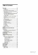
Page 11: ... On Temperature Error 13 On Moisture Condensation 14 On Security 14 On Cleaning 14 On Repacking 14 Disposal of theUnit 14 Features 15 Location and Function ofParts and Controls 16 Front Panel 16 Input Signals and Adjustable Setting ltems 17 Rear Bottom Panel 18 Connecting the Power Cord 19 Initial Setting 20 Using the Menu 22 Adjustment Using the Menus 23 ltems 23 Adjusting and changing the settin...

Page 12: ...er possibility that you experience discomfort 121 Precaution Precautions for connecting this unit with other medical devices Before you utilize this device and or connect this device to any other medical device please be aware of and abide by the following precautions a Before actually using this device for medical practice please check and confirm that you do not experience any discomfort in your...

Page 13: ...ar onthe screen This is not a malfunction When the monitor becomes warm the screen returns to normal The screen and the cabinet become warm during operation This is not a malfunction On a Long Period of Use Duetothe characteristics ofLCD panel displayingstatic images for extended periods or usingthe unitrepeatedly in a high temperature high hurnidity environments may cause image smearing burn in a...

Page 14: ... monitor may be impaired or the finish ofthe surface may be damaged Take care with respect to the following Clean the protection plate surface monitor surface with a 50 to 70 viv concentration of isopropyl alcohol or a 76 9 to 81 4viv concentrationof ethanol using a swab method Wipe the protection plate surface gently wipe using less than 1 N force Stubborn stains may be removed with a softcloth s...

Page 15: ...and Europe have been obtained for this monitor Themonitoris designedfor use in the medicaltreatment field with the sheet switch screen protect panel etc High resolution Full HD panel A Full HD high resolution 1920 x 1080 paneland wide field of view technology enables you to use the monitor under various lightingconditions andin numerous ways installing on the ceiling wall using several monitors to...

Page 16: ...menu Press again to clear the menu buttons Press to select the items and setting values C CUSTOM button 161 Location and Function of Parts and Controls JI Turns on or offthe assigned function You can adjustthe assigned function by pressing the buttons Referto the custom buttons ofthe system configuration menu on page 28 and ofthe default setting on page 29 The following functions are assigned in t...

Page 17: ...or Temperature 0 0 ACC 0 X 5 CTI 0 X 5 Sharpness V 0 0 Sharpness H 0 0 NTSCSetup 0 0 NTSC 480 601 SD Scan Size 0 0 HD ScanSize X X Gamma 0 0 SD Aspect 0 0 Mono 0 X 5 APA X X Shift H Shift V X X DotPitch X X DotPhase X X Sync Detect X X RGB Range X X FlipPattern 0 0 RGB YPbPr X X 0 Can be adjusted set X Cannot be adjusted set 1 Reflected on tbe screen only when tbe SD signal is input 2 Reflected on...

Page 18: ...ts 5 volts for connected external equipment 0 IZI SERIAL REMOTE connector RJ 45 The monitor can be operated according to control commands sent from connected external equipment Connect to the network by using a lOBASE T lO0BASE TX LAN cable non shielded type of5 or more category optional Caution For safety do not connect the connector to peripheral device wiring that might have excessive voltage F...

Page 19: ...ng Always disconnect the power cord before connecting and disconnecting connectors I Warning Using this unit for medical purposes The connectors on this unit are not isolated Do not connect any device other than one which conforms to IEC 60601 1 standards When an information technology device or AV device that uses an altematingcurrent is connected current leakage may result in an electric shock t...

Page 20: ...ge where you intend to use this unit from among the options To set the using area Color Temperature North America Latin America Argentina Latin America Paraguay Latin America Uruguay Latin America Other Africa Australasia Europe Middle East Asia Except Japan NTSC Asia Except Japan PAL Japan 1 Turn on the unit D65 D65 D65 D65 D65 D65 D65 D65 D93 The Area Setting screen appears G AteaSetting NorthAm...

Page 21: ... on the menu and other on screen displays The default menu language is set to English 1 1 rrn on the unit Select the area where you intend to use this unit on the Area Setting screen See page 20 2 The Language Setting screen is displayed 3 l ang eSetttng Engf1sh q t Ei t li lraliano Esp al lol O u h Francals Pycc1 1til Press the or button to select the language and press the button When the confüm...

Page 22: ...ting setting change etc To change the menu language refer to To change the menu language on page 21 TO 2 3 6 1 1 Press the CONTROL button The operation buttons are displayed 2 Press the MENU button 3 The menu selecting screen appears The menu presently selected is shown in blue Menu ColOl ToneAdjunment Q 5 c een Cont ol PIP POP E InputConfiguration 0 System Configur11tlon ii InitialSetup l 3 Prese...

Page 23: ... the monitor memory About the control navigation Depending on thestate theoperating buttonsofthe unit light as shown below White light Operable state Green light Operating state Off Unable to operate Adjustment Using the Menus ltems The screen menu ofthis monitor consists ofthe following items Color Tone Adjustment Gamma Phase Chroma Brightness Contrast Color Temperature Gain R Offset Gain G Offse...

Page 24: ...ting the more greenish the picture The lower the setting the more purplish the picture Adjusts color intensity Tue higher the setting the greater the intensity Tue lower the setting the lower the intensity Adjusts brightness Adjusts contrast Select the color temperature from among D56 D65 D93 l M If the setting is changed Gain R G B Offset and Bias R G B Offset are restored to O respectively Adjus...

Page 25: ...displayed Submenu Shift V Dot Phase Dot Pitch Setting Adjusts the vertical position of the picture A higher setting moves the picture up and a lower setting moves the picture down when an analog PC signal is displayed Adjusts the dot phase Adjust the picture further for a finer picture after APA is adjusted when an analog PC signal is displayed Adjusts the horizontal size ofthe picture with the le...

Page 26: ...Enable Sets to use the signals protected with HDCP Disable Sets to use the signals not protected with HDCP When Disable is set for the signals not protected with HDCP signals are output from the DVI D G connector l M When Disable is set for the signals protected with HDCP 1 images are not displayed 1 HDCP High bandwidth Digital Content Protection is a copyright protection technology using encrypti...

Page 27: ... the content of Status Display is changed On The format and scan mode are always displayed Off The format and scan mode are not displayed Mi Even if the setting is set to Auto or Off theflip pattern is available CID For details about the signal format refer to no signal and incompatible signal displays Input No signal Non compatible signal except for DVI D Non compatible signal DVI D Signal format...

Page 28: ...nitial Setup menu is used to set the default preset value ilä lnltlilSetup B Ef lli i Langu g Engfüh Submenu Language Port A Input Select PortB Input Select Pattern Skip PIP POP PIP Sub Screen Position POPSub Screen Position PORT AHD Clipping Size PORTBHD Clipping Size Setting You can select the menu or message language frorn the following languages English English i pj Chinese B fü t Japanese Ita...

Page 29: ...oblem and as a result eliminate the need to contact technical support The display is colored in green or purple When HDlS is selected perform the RGB YPbPr selection correctly The unit cannot be operated The key protection function is enabled Set the Control Lock setting to Off in the Control Lock menu Tue blackbars appear at the upper and lower positions ofthe display When the signal aspect ratio...

Page 30: ...a 20 3 4 x 11 3 4 23 7 8 inches H 1 920 lots V 1 080 lines 16 9 VIDEO input NTSC PAL connector BNC type 1 1 Vp p 3 dB sync negative VIDEO input connector 4 pin mini DIN 1 Y 1 Vp p 3 dB sync negative C 0 286 Vp p 3 dB NTSC burst signal level 0 3 Vp p 3 dB PAL burst signal level HD15 input connector D sub 15 pin 1 R G B 0 7 Vp p sync positive Sync On Green 0 3 Vp p sync negative Sync 0 3 Vp p 4 0 Vp...

Page 31: ...c shock Class I Protection against harmful ingress of water IPXl only when used vertically Degree of safety in the presence of a flarnmable anesthetic mixture with air or with oxygen or nitrous oxide Not suitable for use in the presence of a flarnmable anesthetic mixture with air or with oxygen or nitrous oxide Mode of operation Continuous Design and specifications are subject to change without no...

Page 32: ...ts Analog signal Signal Input connector format VIDEO S VIDEO NTSC 0 0 PAL 0 0 480 59 94i 480 60i 480 60p 576 S0i 576 S0p 720 59 94p 720 60p 720 S0p 1080 59 94i 1080 60i 1080 SOi Digital signal Signal Input connector format SDI DVI D 480 59 94i 0 480 60p 0 575 S0i 0 576 S0p 0 720 59 94p 0 0 720 60p 0 0 720 S0p 0 0 1080 59 94i 0 0 1080 60i 0 0 1080 SOi 0 0 1080 59 94p 0 1080 60p 0 1080 SOp 0 HD15 CO...

Page 33: ...77 46 875 53 674 48 363 56 476 60 023 68 677 67 500 60 000 63 981 75 000 fH kHz 29 531 36 979 47 297 59 201 61 742 74 077 39 489 47 649 47 368 55 572 66 647 61 719 74 099 63 194 39 518 47 693 fV Sync polar ity IHz Horizontal Vertic al 59 940 Negative Negative 56 250 Positive Positive 60 317 Positive Positive 72 188 Positive Positive 75 000 Positive Positive 85 061 Positive Positive 60 004 Negative...

Page 34: ...input signal Vertical frequency 50 0 Hz to 85 1 Hz Horizontal frequency 31 5 kHz to 75 0 kHz Dot clock 25 175 MHz to 148 5 MHz fV Hz 74 926 59 995 Picture size phase automatic discrimination by the DE Data Enable signal 341 Specifications Sync pol ar ity Horizontal Vertic al Negative Positive Positive Negative ...

Page 35: ... 4 M4 C Length of M4 screws 4 Monitor cabinet Attached object Side When an optional stand SU 600MD is attached 78 3 1 s 28 8 13 16 17 116 5 4 5 s 1 _ 319 12 5 s Unit mm inches Mass Approx 8 7 kg 19 lb 2 9 oz when the optional stand is not installed LMD 2435MD Front When an optional stand SU 600MD is attached 5718 225 s T _ C I 1 350 13 7 s 1 Dimensions 135 ...

Page 36: ...ength ofM4 screws 4 Monitor cabinet Attached object Side When an optional stand SU 600MD is attached 78 3 1 s 28 8 1 3t 6 r 116 5 4 5 s 1 319 12 5 s Unit mm inches Mass Approx 6 7 kg 14 lb 12 oz when the optional stand is not installed 361 Dimensions ...

Page 37: ...IMP 1 Sony Europe B V Da Vlncilaan 7 01 1930 Zaventem Belgium Sony Belgium bijkantoor van Sony Europe B V DaVincilaan 7 D1 1930 Zaventem Belglum Sony Corporation 1 7 1 Konan Mlnato l u Tokyo 108 0075 Japan ...

Reviews: