background image

41

English

1. Note to users ............................................................ 42

1-1. General precautions ........................................... 42
1-2. Handling instructions .......................................... 42
1-3. Cautions on operation ........................................ 43
1-4. Instructions for connecting to

the measuring unit ............................. 43

2. Summary .................................................................. 44

2-1. Features ............................................................. 44
2-2. System structure ................................................ 45

3. Connecting and installating .................................... 46

3-1. Connecting the cables ....................................... 46
3-2. Installing the display unit .................................... 46

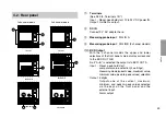
4. Name and function of each part ............................. 47

4-1. Front  panel ........................................................ 47
4-2. Rear panel ......................................................... 49
4-3. Function description ........................................... 50

5. Operation .................................................................. 52

5-1. Initial settings ..................................................... 52
5-2. Various settings ................................................. 56

6. Terminals I/O ............................................................ 60

6-1. Connector pin assignment ................................. 60
6-2. I/O circuitry ......................................................... 61
6-3. Signal timing ...................................................... 62

Contents

7. BCD output (only BCD model) ................................ 63

7-1. Connector pin assignment ................................. 63
7-2. I/O timing ............................................................ 65
7-3. Interface cable ................................................... 66
7-4. Connection circuit .............................................. 67

8. RS-232C Interface (only RS-232C model) .............. 68

8-1. Terminal pin assignment .................................... 68
8-2. Connecting P40 digital printer ............................ 68
8-3. Connecting a personal computer ....................... 69
8-4. RS-232C Interface ............................................. 69
8-5. EXT. IN circuit .................................................... 70
8-6. Output ................................................................ 70
8-7. Commands ......................................................... 71

9. Alarm display/output ............................................... 74

10. Specifications .......................................................... 75

11. Troubleshooting ...................................................... 79

Summary of Contents for LT10 Series

Page 1: ...on description 50 5 Operation 52 5 1 Initial settings 52 5 2 Various settings 56 6 Terminals I O 60 6 1 Connector pin assignment 60 6 2 I O circuitry 61 6 3 Signal timing 62 Contents 7 BCD output only BCD model 63 7 1 Connector pin assignment 63 7 2 I O timing 65 7 3 Interface cable 66 7 4 Connection circuit 67 8 RS 232C Interface only RS 232C model 68 8 1 Terminal pin assignment 68 8 2 Connecting...

Page 2: ...ipment the functions and performance as noted in this manual may not be attained depending upon the operating environmental conditions Make a thorough study of the compatibility in advance 1 Note to users 1 2 Handling instructions Do not open the cover of this device or put your hand inside Otherwise the internal circuit may be broken by static electricity To prevent malfunctions caused by static ...

Page 3: ...nnector be sure to wire the connector correctly Failure to do so may damage the internal circuits Place the display unit more than 0 5 m 20 away from a high voltage source large current source large power relay etc For installation of the display unit avoid a location exposed to chips cutting oil or machine oil If unavoidable take adequate countermeasures Do not put a vinyl cover directly over the...

Page 4: ...5 mm 0 0002 LT11 series 0 001 mm 0 0001 As well as the current value maximum and minimum values and peak to peak values can also be measured Add Sub calculation is standard feature only for 2 channel models Can measure the widths or steps Can carry out Go No Go test on different lots BCD output models Four different upper and lower limits can be stored in memory for the Go No Go comparison Power i...

Page 5: ...P Go No Go Go No Go Go No Go Go No Go Go No Go Go No Go PLC etc Computer Printer P40 etc Display unit Measuring Probe LT10 105 LT11 101 1 channel 205 201 2 channel including Add Sub DT12N 512N DT12P 512P IP64 Compatible 9 V AC Adaptor 12 to 24V Terminal RS 232C RS 232C BCD BCD 105B 101B 1 channel 205B 201B 2 channel including Add Sub 105C 101C 1 channel 205C 201C 2 channel including Add Sub Power ...

Page 6: ...cut out opening in the panel from the front 3 Attach the supplied counter stopper from the rear 4 Press in the counter stopper until it touches the panel Note When attaching the counter stopper to the display unit leave enough space min 30 mm 1 18 between it and the panel Fig 3 3 Connecting and installating Fig 2 Fig 3 Cut out dimensions Panel box Front of display unit Fig 1 68 2 68 1 0 0 4 0 039 ...

Page 7: ... to peak maximum minimum or current values 5 Comparator value setting key Key to enter the mode for setting the comparator upper or lower limit 6 Setting key Set a mode or a value 7 Number selection key Selects the number for the digit chosen 8 Digit selection key Selects the digit to change when setting numeric values On the front panel the LT10 series and LT11 series only differ in the model nam...

Page 8: ...four different comparator upper and lower limit settings CPH1 to CPH4 and CPL1 to CPL4 can be stored in the memory for LT10 105B 205B and LT11 101B 201B LT10 105 205 105C 205C and LT11 101 201 101C 201C have only one setting each Selected channel indicator 2 channel model Choose one of these two Upper A A B Lower B A data from measuring probe input channel A rear of case B data from measuring prob...

Page 9: ...o BCD OUT A Input Reset peak hold start comparator value selection 4 settings measuring mode current value maximum value minimum value peak to peak values selection Output 5 digits Outputs one of the current maximum minimum and peak to peak values selected via the keys on the front panel and the external input Alarm output 1 channel models 2 channel models 1 2 3 4 5 6 7 8 9 10 11 12 13 14 105 101 ...

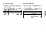
Page 10: ...e selected digit will flash Error is displayed All the numbers for the channel with an error flash Operation performed when reset key is pressed Display is set to zero When a preset value has been set this is recalled Preset value is set to zero Device is cleared and then returnes to the measuring state Automatically carries out initialization to calibrate the device to a new measuring probe Befor...

Page 11: ...ed out by comparing data from the current measuring mode current value maximum value minimum value or peak to peak value to the comparator upper and lower limits This result is displayed on the front panel and output from the terminals See P60 6 Terminals I O Result High Go Low Display Condition Data upper limit Upper limit data lower limit Lower limit data Operation Start on L ON signal from pin ...

Page 12: ...ith the key no changes will be mode until you press the SET key Once the initial setting mode has been entered it is not possible to return to the measuring state partway through Press the MODE key repeatedly to skip the items 5 1 1 Basic settings 1 Setting the display 2 channel models One of the following may be chosen A and B Only A B 2 Setting the resolution or direction channel A One of 0 001 ...

Page 13: ... 0001 are not avaible When the addition A B is chosen the direction for B can be selected but its resolution will be the same as that of A 4 Selecting the start input terminal terminals function See P60 6 Terminals I O Start function When the peak hold is chosen setting this terminal to L ON sets the peak hold value to the current value and restarts the storing procedure Hold function When using t...

Page 14: ...byte Sign space 3rd to 8th bytes Numerical data ex 12 345 Outputting with measurement mode information 1st byte Channel name A or B 2nd byte Current mode N Current value P Peak to peak value I Minimum value A Maximum value 3rd byte Unit M mm I inch 4th byte Sign or 5th to 10th bytes Numerical data ex 00 000 Outputting according to the mode 1 format statistical calculations of the digital printer P...

Page 15: ... Here the EXT IN terminal cannot be used 8 Selecting the output time interval This mode is selected when has been chosen in step 7 is displayed and one of eight intervals can be chosen 0 2 0 5 1 0 5 0 10 20 30 60 300 s 9 Selecting the data transmission format 2 channel models is displayed and one of the following is chosen format a given below format b given below To output from channel A 12 345 a...

Page 16: ...lect a numeral 3 Push SET to set P for A channel flashes 4 Push P to select B channel preset value setting mode B channels sign flashes Single channel models return to the measuring state 5 Same as 2 6 Push SET to set Both A B channel P flashes 7 Push P to returns to the measuring state Both A B channel P lights Note If SET is not pressed the previous setting is kept In the P P measuring mode the ...

Page 17: ...ected mode s indicator flashes 3 Push SET to set Set mode flashes The other channel A modes disappear 4 Push MODE to select the setting mode for channel B Currently set channel B mode flashes 5 Same as 2 6 Push SET to set Modes set for channels A and B flash 7 Push MODE to return to the measuring state Modes set for channels A and B light Note If you do not press SET the previous settings will be ...

Page 18: ... number 3 Push SET to set CPH flashes 4 Push COMP to select the CPL comparator lower limit setting mode Sign of the CPL value flashes 5 Same as 2 6 Push SET to set CPH and CPL flash 7 Push COMP to select the mode for setting the channel B comparator values Single channel models return to the measuring state 8 9 10 Same as 2 3 4 5 6 11 12 13 Push COMP to return to the measuring state RESET SET P MO...

Page 19: ...ng the 4 different setting values is carried out via the BCD connector input terminal When the BCD connector is not connected the setting is CPH1 and CPL1 Note 2 If SET is not pressed the previous setting is maintained Note 3 When the SET key is pressed to set the CPL the sign or of the CPH value may flash This is because the CPH upper limit is less than the CPL lower limit and the device is in th...

Page 20: ...art hold input Reset recall input Main DC power 12 to 24V GND for power Signal name 1 CH model 2 CH model GND HI HI A GO GO A LO LO A Connection prohibited HI B Connection prohibited GO B Connection prohibited LO B GND FG START RESET DC IN 12 to 24V GND GND Rear of display unit Use a shielded cable for connection to the FG pin on the rear of the display unit Prepare a shield cable by yourself GND ...

Page 21: ...t key or external reset recall input Reset recall input L ON sets the measured value to zero When there is a preset value this is recalled Note Even when the L level is held the Go No Go output terminals and the display are not held Main DC power 12 to 24V Use with the pin GND Connect to a 12 to 24V DC power source Use a switching diode with a back voltage of approximately 3 times the supply volta...

Page 22: ...et input 2 7Result evaluation output Note When the start hold terminal 0 s initial setting is the L ON signal will hold the immediately previous Go No Go result and the display Sampling 6 ms 2 CH model 8 ms 1 CH model 0 MAX 6 ms 2 CH model 8 ms 1 CH model Go No Go output and display value I N MIN 5 ms MIN 4 ms OUT GND IN COM 5V 47kΩ 47kΩ 1kΩ Display unit Externally connected device Connection Type...

Page 23: ...e procured Manufactured by Hirose Electric Co LTD DX10 36S Display unit receptacle DX40 36P Plug accessory DX 36 CV Plug case accessory Pin No 1 2 3 4 5 6 7 8 9 10 11 12 13 14 15 16 17 18 Pin No 19 20 21 22 23 24 25 26 27 28 29 30 31 32 33 34 35 36 Signal 1st digit Q1 A Q2 B Q3 C Q4 D 2nd digit Q1 A Q2 B Q3 C Q4 D 3rd digit Q1 A Q2 B Q3 C Q4 D 4th digit Q1 A Q2 B Q3 C Q4 D 5th digit Q1 A Q2 B Sign...

Page 24: ... received from at º and when the READY output at goes L ON the BCD data is output Output logic True logic or false logic can be selected See P53 5 1 2 BCD model True logic L ON is 0 H OFF is 1 Output format Whether to hold the BCD output data or to assume high impedance when there is no DRQ signal input can be selected See P53 5 1 2 BCD model SIGN output Tells whether the output data is positive o...

Page 25: ...BCD output data is held on DRQ becoming H OFF However when the initial setting of pin 0 of the terminals is changed from set at the time of shipping to the hold function of the display and output of terminals is enabled only for pin 0 of the terminals and the DRQ hold function operates only for the BCD output data 7 2 I O timing 1 º Data º DRQ input READ output When Initial setting See P53 for fac...

Page 26: ...dition connect the shielded cable of the connected equipment to frame GND The plug case is connected to FG of LT10 LT11 Connect the braided wire to the case after folding back and securing with the metal clips Assembling the plug provided Fold back the braided wire and secure with the metal clips Cable Case Plug Case I N MIN 5 ms MIN 4 ms I N DATA OUT MAX 50 ms ...

Page 27: ...se the transistors inside the output IC may be damaged GND OUT IN COM COM 74LS06 Display unit Relay Externally connected device Connection Type 2 Input signal rating On VIL MAX 0 5 V when input current IIL 15 mA Off VIH MIN 4 0 V to MAX 26 4 V Input circuit except pin º DRQ TTL level input Input signal rating On VIL MAX 1 0 V when input current IIL 5 mA Off VIH MIN 4 0 V to MAX 26 4 V Display unit...

Page 28: ...cting P40 digital printer Connect the cable that comes with the P40 to the RS 232C connector For P40 refer to the instruction manual for the P40 8 RS 232C Interface only RS 232C model The RS 232C interface can be used for connecting a P40 digital printer sold separately to print measured values or to connect a personal computer to use it to control the display unit See P54 5 1 3 RS 232C model 8 1 ...

Page 29: ...roduct Input resistance 3 to 7 kΩ Input allowable voltage 30 V Input threshold Low 1 2 V High 1 7 V 8 3 Connecting a personal computer Use a DZ252 or DZ253A RS 232C cable sold seperately for connecting personal computers See P71 8 7 Commands Note The shielded cables of the DZ252 and DZ253A connectors are connected to FG of LT10 LT11 The DZ252 and DZ253A connectors for the personal computer side ar...

Page 30: ...d 2 Input to the EXT IN terminal 2 2 2 2 2 Initial setting Mode for shortening the output interval Processed as an interrupt However there must be no chattering in the input signal Data is output after an L level signal has been received 8 5 EXT IN circuit Input circuit TTL level input EXT IN A B EXT IN A B Input signal rating On VIL MAX 1 0 V when input current IIL 5 mA Off VIH MIN 4 0 V to MAX 2...

Page 31: ...te bps 19200 9600 4800 2400 1200 600 MIN A 21 21 21 21 21 21 MIN B 21 21 40 80 160 320 MIN A 3 3 3 3 3 3 MIN B 10 20 40 80 160 320 Unit ms 3 Output at set interval Initial setting Eight intervals available 0 2 0 5 1 0 5 0 10 30 60 and 300 s This interval is set with the initial settings See P54 5 1 3 RS 232C model 4 Commands Data is output by input ASCII code commands For more details see section ...

Page 32: ... the value to zero To recall the preset value input the recall preset value command The data set by the commands given in the table will not be stored by the display unit If the power is turned off the settings must be repeated Provide intervals of at least 50 ms between command inputs 2 Example of data transmission External device display unit To preset 12 345 for A channel AP 12 345 CR LF Displa...

Page 33: ...h the delimiter is selected by the initial setting See P55 step 9 When set to mode even the 2 channel model only outputs the A channel data only 3 The output data format Changing according to the initial settings See P54 1 Normal condition Initial setting Normal output set at time of shipping 1st byte Channel name A or B 2nd byte Sign space 3rd to 8th bytes Numerical data ex 12 345 Initial setting...

Page 34: ...n Reset Fix problem and reset Reset Fix problem and reset Limit input to 5 digits and reset Move the measuring unit at least 1 mm and reset Cause The measuring probe was exchanged with the power on Measuring probe is not connected or connection has been cut The measuring probe s spindle exceeded the maximum acceleration Abnormality in measuring probe s output signal or connection has been cut Valu...

Page 35: ... set with key switches Result evaluation LED display and output by terminals open collector Up to 4 values can be set for comparator key input Switched with BCD terminal Up to 4 values can be set for comparator key input Switched with BCD terminal Set with RS 232C command Set with RS 232C command Input BCD terminal Input BCD terminal RS 232C command RS 232C command 2 DC IN DC 9 V 600 mA or higher ...

Page 36: ...H OFF BCD alarm terminal H OFF BCD alarm terminal H OFF Resolution direction comparator value preset value modes 3 1 W Approx 210 g BCD sign Data signalling rate etc BCD sign Data signalling rate etc Operating temperature 0 to 40 C Storage temperature 10 to 50 C 5 2 W Approx 250 g 2 9 W Approx 190 g 2 0 W Approx 205 g 2 9 W Approx 215 g Terminals DC10 8 to 26 4 V DC IN jack DC 9V AC power adapter ...

Page 37: ...BCD output connector plug 1 LT10 105B LT11 101B only 2 LT10 205B LT11 201B only Options Digital printer P40 Connector cable for personal computer Personal computer side 9pin Dsub connector DZ252 Personal computer side 25pin Dsub connector DZ253A Foot switch PZ201 ...

Page 38: ... 30 2 R 2 60 2 36 1 0 04 15 0 59 68 2 68 1 0 0 4 0 039 0 016 68 2 68 1 0 0 4 0 039 0 016 4 R1 or less LT11 mm M A X M I N P P C P H1 2 3 4 A B P mm M A X M I N P P C P L1 2 3 4 BA P RESET A RESET B SET P MODE CONP 72 2 83 72 2 83 8 0 31 68 2 68 71 8 2 83 68 2 68 79 5 3 13 Counter stopper Unit mm inch ...

Page 39: ...le Check for the proper range of power voltage Reset the unit after moving the measuring probe at least 1 mm Has the measuring probe s cable been disconnected Has the maximum acceleration for the measuring probe been exceeded Perform resetting operation First carry out the reset procedure Was the measuring probe exchanged with the power on Is the measuring unit s connector locked Is the measuring ...

Page 40: ...at may affect accuracy Any trouble due to machine adjustment deflection on play Check to see if the temperature difference between the measuring unit machine and workpiece is great L L L L L Cleaning To remove heavy dirt Use dry cotton cloth To clean the display and casing Use diluted neutral detergent Do not use LT20 mm M A X M I N P P C P H1 2 3 4 P RESET SET P MODE COMP mm M A X M I N P P C P L...

Page 41: ...96 6 Ein Ausgänge der Klemmenleiste 100 6 1 Stiftbelegung der Steckverbindung 100 6 2 Ein Ausgangsschaltung 101 6 3 Signal Taktgebung 102 7 BCD Ausgang nur BCD Modell 103 7 1 Stiftbelegung der Steckverbindung 103 7 2 Signal Taktgebung 105 7 3 Schnittstellenkabel 106 7 4 Anschlußschaltung 107 8 RS 232C Schnittstelle nur RS 232C Modell 108 8 1 Stiftbelegung der Steckverbindung 108 8 2 Benutzung des ...

Page 42: ...dapters darauf daß die Spannung innerhalb des vorgeschriebenen Bereiches liegt 1 1 Allgemeine Vorsichtsmaßnahmen Beim Einsatz von Geräten von Sony Manufacturing Systems Corporation sind die folgenden allgemeinen Vorsichtsmaßnahmen zusätzlich zu den in der vorliegenden Anleitung jeweils speziell angegebenen Warnhinweisen zu beachten um einen korrekten Einsatz des Geräts zu gewährleisten Vor und wäh...

Page 43: ...chaltet wird 1 mm oder mehr Verwenden Sie keine für den Anschluß gesperrten Kontaktstifte als Relaisstifte Achten Sie bei Anschluß des BCD Steckers auf korrekte Verdrahtung des Steckers Bei Mißachtung können die internen Schaltungen beschädigt werden Die Anzeigeeinheit in einem Abstand von mindestens 0 5 m von Hochspannungsquellen Starkstromquellen Leistungsrelais usw aufstellen Bei der Installati...

Page 44: ... 001 mm Außer dem aktuellen Wert können auch Maximalwert Minimalwert und Spitze Spitze Wert gemessen werden Das Modell mit Zweikanal Ein Ausgabe ist serienmäßig mit einer Funktion zur ADD SUB Berechnung ausgestattet die zur Messung der Breite und Höhe von Bauteilen verwendet werden kann Durchführung von Gut Ausschuß Auswertung an verschiedenen Losen möglich Modelle mit BCD Ausgang Für den Ergebnis...

Page 45: ...schuß Gut Ausschuß Gut Ausschuß Gut Ausschuß Gut Ausschuß Folgesteuerung usw Computer Drucker P40 o ä Anzeigeeinheit Meßsonde LT10 105 LT11 101 Ein Kanal 205 201 Zwei Kanäl einschl ADD SUB DT12N 512N DT12P 512P Kompatibel mit IP64 9 V Netzadapter 12 bis 24V Anschlußklemmen RS 232C RS 232C BCD BCD 105B 101B Ein Kanal 205B 201B Zwei Kanäl einschl ADD SUB 105C 101C Ein Kanal 205C 201C Zwei Kanäl eins...

Page 46: ...isplay Einheit von vorn in die ausgeschnittene Öffnung des Bedienungspults einführen 3 Den mitgelieferten Zähleranschlag von hinten anbringen 4 Den Zähleranschlag hineindrücken bis er die Tafel berührt Hinweis Lassen Sie beim Anbringen des Zähleranschlags an der Anzeigeeinheit genügend Platz mindestens 30 mm zwischen dem Anschlag und der Tafel Abb 3 3 Einbau und Anschluß Abb 1 Vorderseite der Disp...

Page 47: ...Wert Maximalwert Minimalwert oder aktuellen Wert 5 Taste zur Einstellung des Komparatorwertes Diese Taste dient zur Aktivierung der Betriebsart zur Einstellung der Ober oder Untergrenze des Komparators 6 Eingabetaste Dient zur Eingabe der gewählten Betriebsart oder der eingestellten Werte 7 Zahlenwahltaste Dient zur Wahl der gewünschten Zahl für die angewählte Ziffer 8 Ziffernwahltaste Dient zur W...

Page 48: ...rn stellen die Untergrenze dar Beim LT10 105B 205B und LT11 101B 201B können bis zu vier verschiedene Einstellungen für die Komparator Ober und Untergrenze CPH1 bis CPH4 und CPL1 bis CPL4 gespeichert werden Die Modelle LT10 105 205 105C 205C und LT11 101 201 101C 201C verfügen jeweils nur über eine Einstellung Anzeige für Komparator Obergrenze Anzeige des gewählten Kanals Zweikanalmodell Eine der ...

Page 49: ...atte jeweils dem Ausgang BCD OUT A B Wenn A B gewählt wird werden die Signale an BCD OUT A ausgegeben Eingang Rückstellung spitzenwertarretierungsstart Wahl des Komparatorwertes vier Arten Meßmodus wahl Aktuelle Wert Maximalwert Minimalwert oder Spitze Spitze Wert Ausgang 5 Stellen offener Kollektor Der durch die Tasten an der Frontplatte und den externen Eingang gewählte aktuelle Wert Maximalwert...

Page 50: ...aste Display Einheit Meßmodus Aktueller Wert Maximalwert Minimalwert Spitze Spitze Wert Voreinstellungsmodus P und die gewählte Ziffer blinken Error wird angezeigt Alle die Ziffern für den Kanal mit einem Fehler blinkt Operation bei Betätigung der Rückstelltaste Die Anzeige wird auf Null zurückgestellt Wenn ein Voreinstellwert eingegeben worden ist wird dieser abgerufen Voreinstellwert wird auf Nu...

Page 51: ...Voreinstellwertes ist unter 5 2 1 Einstellen des Voreinstellwertes auf Seite 96 beschrieben 4 3 3 Ergebnisauswertung Die Gut Ausschuß Auswertung erfolgt durch Vergleichen der Daten des gewählten Meßmodus aktueller Wert Maximalwert Minimalwert oder Spitze Spitze Wert mit der Ober und Untergrenze des Komparators Dieses Ergebnis wird auf der Frontplatte angezeigt und an den Klemmen ausgegeben Seite 1...

Page 52: ... Nachdem der Anfangseinstellungsmodus aktiviert worden ist kann zwischendurch nicht auf den Meßmodus umgeschaltet werden Zum Überspringen der einzelnen Punkte die Taste MODE mehrmals drücken 5 1 1 Grundeinstellungen 1 Einstellung der Anzeige Zweikanalmodelle Die folgenden Möglichkeiten stehen zur Auswahl A und B Nur A B 2 Einstellung der Auflösung oder Richtung Kanal A Die Einstellungen 0 001 0 00...

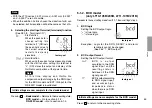
Page 53: ...ungen für das Standard Modell abgeschlossen Drücken von MODE Standard Modell Rückkehr zum Messungszustand BCD Modell zu Abschnitt 5 1 2 gehen RS 232C Modell zu Abschnitt 5 1 3 gehen 5 1 2 BCD Modell nur LT10 105B 205B L11 101B 201B Weiterrücken zum nächsten Einstellmodus von 5 1 1 Grundeinstellungen Schritt 4 1 BCD Logik Einstellen der Logik des offenen Kollektors des BCD Ausgangs bedeutet wahr be...

Page 54: ... RS 232C Modell nur LT10 105C 205C LT11 101C 201C Weiterrücken zum nächsten Einstellmodus von 5 1 1 Grundeinstellungen Schritt 4 1 Einstellen des Ausgabeformats Normale Ausgabe 1 Byte Kanal A oder B 2 Byte Vorzeichen Leerstelle oder 3 bis 8 Byte Numerische Daten Exemple 12 345 Ausgabe mit Meßmodus Information 1 Byte Kanal A oder B 2 Byte Aktueller Modus N Aktueller Wert P Spitze Spitze Wert I Mini...

Page 55: ...urückzuschalten 5 Einstellen der Parität wird angezeigt und die P a r i t ä t k a n n e i n o d e r ausgeschaltet werden Keine Parität Parität Hinweis Wenn die Datenlänge eingestellt auf 7 Bit in Schritt 3 Parität wählen 6 Wahl der ungeraden oder geraden Parität Es erfolgt eine Umschaltung auf diese Betriebsart wenn im obigen Schritt gewählt wird Ungerade Parität Gerade Parität 7 Wahl der Funktion...

Page 56: ... drücken um einzugeben P für Kanal A blinkt 4 P drücken um das Voreinstellwert Eingabemodus für Kanal B zu wählen Im Falle des Einkanalmodells wird auf den Messungszustand umgeschaltet 5 Wie bei 2 6 SET drücken um einzugeben P für Kanal A und B blinkt 7 P d r ü c k e n u m z u m M e s s u n g s z u s t a n d zurückzugehen P für Kanal A und B leuchtet Hinweis Wenn SET nicht gedrückt wird bleibt die...

Page 57: ...sart blinkt Die anderen Betriebsartanzeigen für Kanal A verschwinden 4 MODE drücken um das Eingabemodus für Kanal A zu wählen Die Anzeige der gegenwärtig eingestellten Betriebsart für Kanal B blinkt 5 Wie bei 2 6 SET drücken um einzugeben Die Anzeigen der für Kanal A u n d B e i n g e s t e l l t e n Betriebsarten blinken 7 MODE drücken um zum Messungszustand zurückzugehen Die Anzeigen der für Kan...

Page 58: ...n 3 SET drücken um einzugeben CPH blinkt 4 COMP drücken um das Einstellmodus der CPL Komparator Untergrenze zu wählen Das Vorzeichen des CPL Wertes blinkt 5 Wie bei 2 6 SET drücken um einzugeben CPH und CPL blinken 7 COMP d r ü c k e n u m d a s E i n s t e l l m o d u s d e s Komparatorwertes für Kanal B zu wählen Einkanal Modell kehrt zum Messungszustand zurück 8 9 10 Wie bei 2 3 4 5 6 11 12 13 ...

Page 59: ...sses Wenn der BCD Anschluß nicht benutzt wird sind die Einstellwerte Kombinationen von CPH1 und CPL1 Hinweis 2 Falls SET nicht gedrückt wird bleiben die vorherigen Einstellungen erhalten Hinweis 3 Wenn zur Eingabe des CPL Wertes die Taste SET gedrrückt wird kann es vorkommen daß das Vorzeichen oder des CPH Wertes blinken Dies liegt daran daß der CPH Wert Obergrenze kleiner als der CPL Wert Untergr...

Page 60: ...e 90 4 3 Beschreibung der Funktionen Pol Nr 1 2 3 4 5 6 7 8 9 10 11 12 13 14 Beschreidung Ausgang für Gut Ausschußauswertung High A CH Go A CH Low A CH High B CH Go B CH Low B CH Rahmenmasse Eingang für Start Halten Eingang für Rückstellung Abruf Gleichspannungseingang 12 bis 24 V für Stromversorgung Rückseite der Display Einheit Verwenden Sie ein abgeschirmtes Kabel für die Verbindung zum Stift F...

Page 61: ...ngabe nicht bewirkt werden Eingang für Rückstellung Abruf L ON stellt den gemessenen Wert auf Null Wenn ein Voreinstellwert vorhanden ist wird dieser abgerufen Hinweis Auch wenn das L Niveau gehalten wird werden die Gut Ausschußausgabe Klemme und die Anzeige nicht abgehalten Gleichspannungseingang 12 bis 24 V In Verbindung mit Stift GND verwenden An eine Stromquelle von 12 bis 24 V Gleichspannung ...

Page 62: ...swertungsergebnis und der angezeigte Wert gehalten Sampling 6 ms Zweikanalmodell 8 ms Einkanalmodell 0 Anzeige der Gut Ausschußauswertung MAX 6 ms Zweikanalmodell 8 ms Einkanalmodell Eingangssignal Kenndaten Ein VIL MAX 1 0 V Eingangsstrom IIL 5 mA Aus VIH MIN 4 0 V bis MAX 26 4 V Eingangsschaltung Stifte 0 TTL Pegeleingang I N MIN 5 ms MIN 4 ms 0 Eingang für Start Rückstellung Display Einheit OUT...

Page 63: ... für Maximalwert Minimalwert Spitze Spitze Wert ausgegeben Außerdem gibt es Funktionen für Alarmausgabe Start oder R ü c k s t e l l u n g s e i n g a b e u n d E i n g a b e d e r Komparatorwertwahl und Meßmodus wahl Eingabe aktueller Wert Maximalwert Minimalwert Spitze Spitze Wert Alle Ausgänge entsprechen IC 74LS06 mit offenem Kollektor Beim Modell Zweikanalmodell weisen Kanal A und B dieselben...

Page 64: ...ahr L ON ist 0 H OFF ist 1 Ausgabe formats Es ist wahlbar die ausgegebene BCD Daten zu halten oder wenn es kein DRQ Signal gibt die den hochomigen Status annehmen zu lassen Siehe Seite 93 5 1 2 BCD Modell 1 Ziffer Meßmodus Wahl Eingang Die Wahl von aktueller Wert Maximalwert Minimalwert oder Spitze Spitze Wert ist möglich Vorzeichen Ausgabe Gibt an ob die ausgegebenen Daten positiv oder negativ si...

Page 65: ...können gewählt werden Haltefunktion der DRQ Anzeige Ausgabe Während das DRQ Signal L ON ist werden Anzeige und Ausgabe BCD Daten Gut Ausschußauswertungs von Klemmenleiste gespeichert Wenn das BCD Ausgabe bei den Anfangseinstellungen auf eingestellt wurde werden nur die BCD Ausgabedaten beim L Niveau von DRQ gehalten Wird jedoch die werkseitige Anfangseinstellung des Stiftes 0 der Klemmenleiste von...

Page 66: ...menmasse Das Steckergehäuse wird mit FG von LT10 LT11 verbunden Verbinden Sie die Abschirmung mit dem Gehäuse nachdem Sie sie zurückgeschlagen und mit den Metallklemmen gesichert haben Zusammenbau des mitgelieferten Steckverbinders Gehäuse Steckverbinder Die Abschirmung zurückschlagen und mit den Metallklemmen sichern Kabel Gehäuse Start Rückstellungs Eingabe Komparatorwertwahl Eingabe I N MIN 5 m...

Page 67: ... Versorgungsspannung COM ist 80 V Haltespannung bei einer Versorgungsspannung von 24 V Eingangssignal Kenndaten Ein VIL MAX 0 5 V Eingangsstrom IIL 15 mA Aus VIH MIN 4 0 V bis MAX 26 4 V Einigangsschaltung außer Stift º DRQ TTL Pegeleingang Eingangssignal Kenndaten Ein VIL MAX 1 0 V Eingangsstrom IIL 5 mA Aus VIH MIN 4 0 V bis MAX 26 4 V GND OUT IN COM COM 74LS06 Display Einheit Extern angeschloss...

Page 68: ... TXD RXD RTS CTS DSR Anschluß auf der Geräteseite EXT IN Durch Eingabe des Signals L ON werden die gemessenen Werte über den RS 232C Anschluß ausgegeben Der gesondert Fußschalter PZ201 Option wird an diese Buchse angeschlossen Andere verwendbare Kabel mit Ministeckern sind z B Sony s Lautsprecherkabel RK S100 Ministecker offenes Ende usw Siehe Seite 110 8 6 Ausgabeverfahren 8 2 Benutzung des Digit...

Page 69: ...Mini DIN 8poligen Mini DIN Abgeschirmtes Kabel 25poligen Dsub DZ252 DZ253A Personal computer Personal computer 8 4 RS 232C Schnittstelle 1 Signal übereinstimmung mit EIA RS232C Signale Asynchron Start Stopp System Vollduplex Datenübermittlungs geschwindigkeit 600 1200 2400 4800 9600 19200 bps Datenlänge Umschaltbar zwischen 7 oder 8 Bit Parität Keine ungerade oder gerade Parität wählbar Stopp Bits...

Page 70: ...t Die Daten werden A ms nach Empfang eines Signals mit Pegel L ausgegeben 2 Eingabe in die EXT IN Buchse 2 Anfangseinstellung Dieser Modus wird zur Verkürzung des Ausgabeintervalls verwendet Verarbeitung als Interrupt Das Eingabesignal muß jedoch frei von Störungen sein Die Daten werden nach Empfang eines Signals mit Pegel L ausgegeben EXT IN A B EXT IN A B Eingangssignal Kenndaten Ein VIL MAX 1 0...

Page 71: ... werkseitige Einstellung auf geändert wird nur Stift 0 der Klemmenleiste die Haltefunktion haben die angezeigten Werte und die Ausgabe der Klemmenleiste zu halten während die Haltefunktion des EXT IN Signal nur für die RS 232C Daten wirksam ist 8 7 Befehlsübersicht 1 Befehlstabelle Umwandlung in ASCII Codes Befehl P P MAX MIN REAL RCL RES START P CH CL r R KEYON KEYOFF Operation Umschaltung auf Sp...

Page 72: ...ll gestellt Um den Voreinstellwert abzurufen ist der Befehl Voreinstellwert abrufen einzugeben Die durch die obigen Befehle festgelegten Daten werden nicht durch die Display Einheit gespeichert Wenn die Stromversorgung ausgeschaltet wird müssen die Einstellungen wiederholt werden Stellen Sie zwischen Befehleingaben Abstände von mindestens 50 ms 2 Beispiel der Datenübertragung Externes Gerät Displa...

Page 73: ...en oder mit dem Begrenzer aufgeteilt werden Siehe Seite 95 Schritt 9 Bei Einstellung auf modus gibt selbst das Zweikanal Modell nur Daten des Kanals A aus 3 Ausgangsdaten formats Das Ausgangsdatenformat hängt von Anfangseinstellungen ab Siehe Seite 94 1 Normalzustand Anfangseinstellungen Normale Ausgabe werkseitige Einstellung 1 Byte Kanal A oder B 2 Byte Vorzeichen Leerstelle oder 3 bis 8 Byte Nu...

Page 74: ...chlossen oder Verbindung ist unterbrochen Die Spindel der Meßsonde hat die Höchstgeschwindigkeit überschritten Unregelmäßigkeit im Ausgangssignal der Meßsonde oder Unterbrechung der Verbindung Wert hat fünf Stellen überschritten Eine Initialisierung ist erforderlich um die neue Kombination von Display Einheit und Meßsonde zu eichen Ausgabe Gegenstand Meßsonde ist nicht angeschlossen oder Verbindun...

Page 75: ...D Anzeige bzw Ausgabe durch Klemmenleiste offener Kollektor Ein Ausgabe Festlegung von bis zu vier Komparatorwerten Tasten Eingabe Umschaltung mittels BCD Klemme Festlegung von bis zu vier Komparatorwerten Tasten Eingabe Umschaltung mittels BCD Klemme 2 DC IN Buchse Netzadapter einer Leistung von DC 9 V 600 mA oder höher mit Normsteckern 1 Klemmenleiste Eingang Rückstellung Start der Spitzenwertar...

Page 76: ...lbar Umschaltung möglich 2400 m s2 1500 m s2 60 m min Wahl von A B A B B A mittels Richtungseinstellung möglich Beschleunigungs oder Pegelüberlauf Anzeige auf LCD oder Komparatorausgänge der Klemmenleiste sind alle H OFF BCD Alarmklemme H OFF BCD Alarmklemme H OFF Auflösung Richtung Komparatorwert Voreinstellwert Betriebsarten Datenübermittlungs geschwindigkeit usw Datenübermittlungs geschwindigke...

Page 77: ...ußstecker für BCD Ausgang 1 nur LT10 105B LT11 101B 2 nur LT10 205B LT11 201B Option Digitaler Drucker P40 Anschlußkabel für Personal Computers Personalcomputers seite 9poliger Dsub Stecker DZ252 Personalcomputers seite 25poliger Dsub Stecker DZ253A Fußschalter PZ201 ...

Page 78: ...pult 68 1 0 0 4 68 1 0 0 4 4 R1 oder weniger 68 1 74 68 88 78 73 16 33 2 R 2 60 1 15 LT11 mm M A X M I N P P C P H1 2 3 4 A B P mm M A X M I N P P C P L1 2 3 4 BA P RESET A RESET B SET P MODE CONP 72 72 8 68 71 8 68 79 5 Zähleranschlag Einheit mm ...

Page 79: ...tten worden Ist die Meßsonde starken Erschütterungen ausgesetzt worden Eine Rückstellung vornehmen Ist die Meßsonde bei eingeschalteter Stromversorgung ausgewechselt worden Zuerst das Rückstellverfahren ausführen Ist der Steckverbinder der Meßsonde gesichert Hat sich das Kabel der Meßsonde gelöst Eine einwandfrei funktionierende Meßsonde anschließen und eine Rückstellung vornehmen Ist der Voreinst...

Page 80: ...trächtigt wird Störungen durch Maschineneinstellung Durchbiegung oder Spiel Prüfen ob die Temperaturedifferenz zwischen Maßstaß Maschine und Werkstück zu groß ist L L L L L Reinigung Zum Entfernen hartnäckigen Schmutzes Einen trockenen Baumwoll lappen verwenden Reinigung der Anzeige und des Gehäuses Ein verdünntes neutrales Reinigungs mittel verwenden Nicht verwenden LT20 mm M A X M I N P P C P H1...

Reviews: