28
English
1.
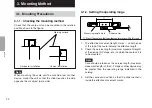
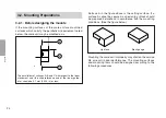
Check the mounting surfaces of the scale unit and
slider.
• Check that the mounting surfaces are machined
surfaces with a roughness of 25 S or more.
• The mounting surfaces of the scale unit and slider
should be planar (maximum difference 0.1 mm
[0.004 in]).
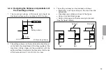
• When providing the setting surfaces on the machine,
check that the parallelism between the machine
guide M and the setting surfaces is 0.1 mm (0.004
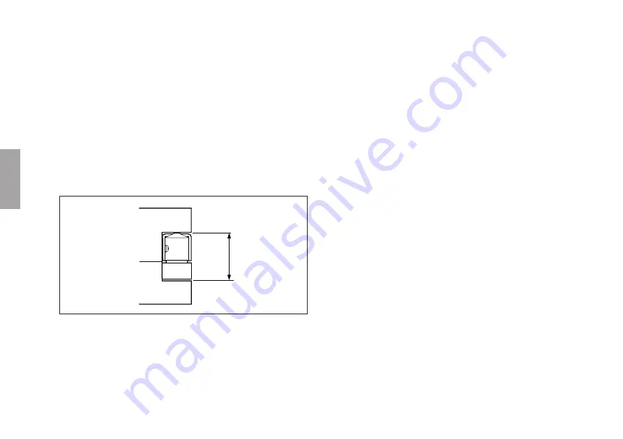
in)/M or less. Also check that the gap between the
scale unit and slider setting surfaces is 12.7 ±0.1 mm
(0.5 ±0.004 in).
3.
Lock the scale unit.
• When setting surfaces are provided, press the scale
unit against the setting surfaces of the machine and
then tighten the screws with a tightening torque of
0.15 N•m (1.5 kgf•cm).
• If there are no setting surfaces, position the setting
surfaces on both ends of the scale unit so that they
are parallel to within 0.1 mm using a dial gauge and
then tighten the screws in the same manner.
Check that the gap between the surfaces is 12.7 ±0.1
mm (0.5 ±0.004 in).
4.
Lock the slider
• When setting surfaces are provided, press the slider
against the setting surfaces of the machine and then
tighten the screws with a tightening torque of 0.15
N•m (1.5 kgf•cm).
• If there are no setting surfaces, set the slider in the
slider holder, press it against the scale unit, and then
tighten the screws in the same manner.
5.
Remove the slider holder
• Remove the three M1.4 screws securing the slider
holder and remove the slider holder.
• Save the removed slider holder and screws for future
use.
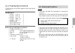
6.
Affix the blindfold label
• Affix the blindfold label so that it covers the two M1.4
screw holes.
12.7±0.1
(0.5 ±0.004 in)
2.
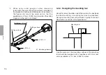
Provisionally secure the scale unit and slider.
• Move the operating parts of the machine so that the
mounting surface of the slider comes roughly below
the center of the stroke. Then provisionally secure
the scale unit using the suPS2
×
4 screws
and the slider using the +PS2
×
8 screws.
• Next, loosen the three mounting screws attached to
the scale unit.

