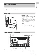


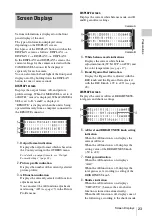

Parts Identifications
14
Ov
e
rv
ie
w
3.
DISPLAY button
4.
CAMERA SEL (camera selection) button
5.
6.
PROFILE SEL (profile selection) + and –
buttons
7.
BRIGHTNESS knob
8.
AREA SEL (light measurement area
selection) button
9.
AE (automatic exposure) button
10.
White balance adjustment section
11.
BLUE (blue gain) knob
12.
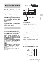
1.
MENU button
2.
SEL/SET knob
3.
CANCEL button
4.
PICTURE PROFILE button
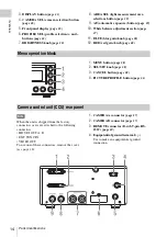
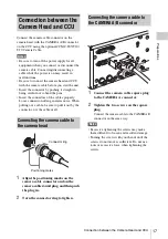
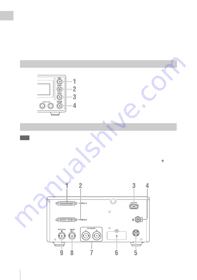
Note
When the unit is shipped from the factory,
connector covers are attached to the following
connectors.
• HD SDI OUT A, B
• EXT SYNC IN
• VIDEO OUT
To use one of these connectors, remove the cover
.
1.
CAMERA A connector
2.
3.
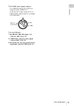
REMOTE connector (D-sub 9-pin, RS-
232C)
4.
Equipotential ground terminal ( )
Use to make an equipotential ground
connection.
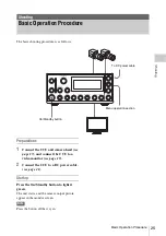
Menu operation block
Camera control unit (CCU) rear panel
Summary of Contents for MCC3000MT
Page 56: ...Sony Corporation ...


