II-51
Audio Setup (Audio)
Ch
ap
te
r 8
Se
tu
p (
[S
e
tu
p
] Menu)
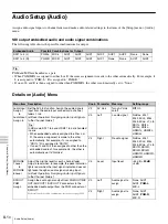
SDI OUT
AUX1
Assign
Assign the audio signals output from PGM OUT/MIX
OUT/AUX OUT 1/AUX OUT 2 connectors to the
embedded audio output from the AUX 1 connector of
SDI OUT.
For details on the possible combinations for output, see page II-50.
V3
Left
Audio signal to
assign
None
, AUX1,
AUX2, PGM-L,
MIX-L
V4
Right
Audio signal to
assign
None
, AUX1,
AUX2, PGM-R,
MIX-R
SDI OUT
AUX2
Assign
Assign the audio signals output from PGM OUT/MIX
OUT/AUX OUT 1/AUX OUT 2 connectors to the
embedded audio output from the AUX 2 connector of
SDI OUT.
For details on the possible combinations for output, see page II-50.
V3
Left
Audio signal to
assign
None
, AUX1,
AUX2, PGM-L,
MIX-L
V4
Right
Audio signal to
assign
None
, AUX1,
AUX2, PGM-R,
MIX-R
SDI OUT
MULTI
VIEWER
Assign
Assign the audio signals output from PGM OUT/MIX
OUT/AUX OUT 1/AUX OUT 2 connectors to the
embedded audio output from the MULTI VIEWER
connector of SDI OUT.
For details on the possible combinations for output, see page II-50.
V3
Left
Audio signal to
assign
None
, AUX1,
AUX2, PGM-L,
MIX-L
V4
Right
Audio signal to
assign
None
, AUX1,
AUX2, PGM-R,
MIX-R
Audio
Output
Delay 1
Allows you to delay the audio output from the PGM
OUT and MIX OUT connectors on a frame basis. If
the output video is delayed with respect to the audio,
you can delay the audio to synchronize it with the
video.
Note
Adjusting the delay time may result in noise being
generated.
V3
PGM
Delay time for
audio output
from PGM OUT
connector
0.00 to 7.50 (
1.00
)
V4
MIX
Delay time for
audio output
from MIX OUT
connector
0.00 to 7.50 (
1.00
)
Audio
Output
Delay 2
Allows you to delay the audio output from the AUX
OUT 1 and 2 connectors on a frame basis. If the
output video is delayed with respect to the audio, you
can delay the audio to synchronize it with the video.
Note
Adjusting the delay time may result in noise being
generated.
V3
AUX1
Delay time for
audio output
from AUX OUT 1
connector
0.00 to 7.50 (
1.00
)
V4
AUX2
Delay time for
audio output
from AUX OUT 2
connector
0.00 to 7.50 (
1.00
)
Output
Level
Adjust the level of audio output to each output
destination.
Tip
The output level of the audio output from the SDI
OUT PGM connector can be adjusted with the
program fader in the audio control block.
V2
MIX
Output level from
MIX OUT
connector
–
∞
to +10 dB
(
0 dB
)
V3
AUX1
Output level from
AUX OUT 1
connector
–
∞
to +10 dB
(
0 dB
)
V4
AUX2
Output level from
AUX OUT 2
connector
–
∞
to +10 dB
(
0 dB
)
Oscillator
You can make the settings for outputting the
oscillator signal used for adjustment.
Tip
If other than “Off” is selected for [Freq] when the
output destination of the oscillator signal is set in
[Term], the DIM button lights and the output level for
the headphones or monitor is automatically reduced.
V2
Freq
Frequency of
oscillator signal
Off
, 100 Hz,
440 Hz, 1 kHz,
10 kHz
V3
Level
Output level of
oscillator signal
–
∞
to 0 dB
(
–20 dB
)
V4
Term
Terminal of
oscillator signal
None,
PGM
, MIX,
AUX1, AUX2, All
(all output
destinations)
Menu item Description
Knob Parameter Meaning
Setting range
Summary of Contents for MCS-8M
Page 64: ...Sony Corporation ...


