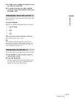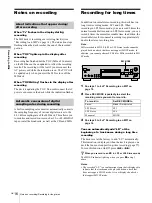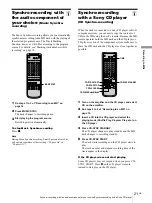
Display window description
8
GB
L
o
ca
tion and Func
tion of
Contr
o
ls
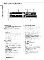
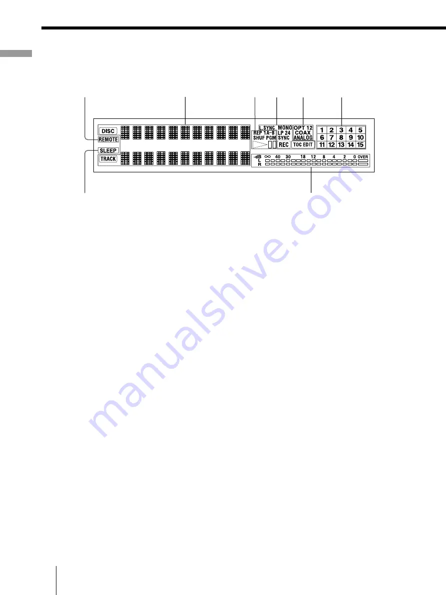
Display window description
A
REMOTE indicator
Lights when the MD is being controlled by an external
device connected to the deck.
B
Disc name and track name indicators display
DISC indicator
Lights when the disc information (etc.) is shown.
Name display
Displays disc and track names, Edit Menu parameters,
and Setup Menu parameters (etc.).
The track name appears instead of the disc name
during play. When the MD or the track has no name,
“No Name” appears.
TRACK indicator
Lights when the track information (etc.) is shown.
C
Playback indicators
REP indicators (26)
Light when the deck is set to Repeat Play.
•
“REP” lights when the deck is set to repeat the entire
disc.
•
“REP 1” lights when the deck is set to repeat just
one track.
•
“REP A-B” lights when the deck is set to repeat a
specific portion within a track.
SHUF indicator (27)
Lights when the deck is set to Shuffle Play.
PGM indicator (27)
Lights when the deck is set to Program Play.
HS
indicator
Lights during playing or playing pause.
D
Recording and editing indicators
L.SYNC indicator (19)
Lights when the deck is set to assign track numbers
automatically during analog recording.
Rec mode indicators (16)
These indicators turn off during stereo recording/
playback.
•
“MONO” lights when the deck is set to Monaural
Recording mode or playing an MD recorded in
Monaural Recording mode.
•
“LP2” lights when the deck is set to LP2 Stereo
Recording mode or playing an MD recorded in LP2
Stereo Recording mode.
•
“LP4” lights when the deck is set to LP4 Stereo
Recording mode or playing an MD recorded in LP4
Stereo Recording mode.
SYNC indicator (21)
Lights during synchro-recording.
REC indicator
Lights during recording.
TOC indicators (16) (31)
•
“TOC” lights to indicate the presence of TOC data
that has not been written to the disc. “TOC” flashes
when the TOC data is being written.
•
“TOC EDIT” lights during edit operations.
E
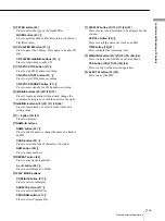
INPUT indicators (14)
•
“OPT1” lights when the program source is
connected to the DIGITAL OPTICAL IN1
connector.
2
3
1
4
5
6
7
8


