background image

67

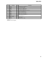
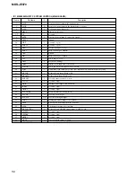
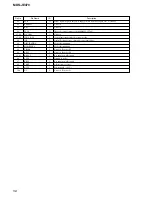
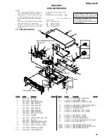
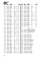
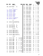
Ref. No.

Part No.

Description

Remarks

Ref. No.

Part No.

Description

Remarks

MDS-JE470

MAIN

<FERRITE BEAD>

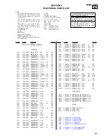
FB460

1-414-093-11 FERRITE

0UH

FB465

1-414-093-11 FERRITE

0UH

<IC>

IC1

6-800-020-01 IC   M30803MG-107FP

IC310

8-759-634-51 IC   NJM4558D

IC360

8-759-634-51 IC   NJM4558D

IC370

8-759-634-51 IC   NJM4558D

IC401

8-759-445-59 IC   BA033T

IC406

8-759-481-02 IC   M62016L

IC411

8-759-231-53 IC   M5F7805L

IC421

8-759-633-42 IC   M5293L

IC440

8-759-633-65 IC   M54641L

IC500

8-759-579-68 IC   AK4524

IC550

8-759-591-61 IC   TC7WHU04FU(TE12R)

IC600

8-759-917-18 IC   SN74HCU04AN

IC611

8-749-012-70 IC   GP1F38R

<JACK>

J300

1-784-429-11 JACK, PIN 4P (ANALOG IN/OUT)

J800

1-580-394-11 CONNECTOR, DIN 6P (PC LINK)

<COIL>

L555

1-414-142-11 INDUCTOR

1uH

L611

1-410-509-11 INDUCTOR

10uH

L653

1-412-473-21 INDUCTOR

0uH

L657

1-412-473-21 INDUCTOR

0uH

L804

1-410-324-11 INDUCTOR

4.7uH

<TRANSISTOR>

Q181

8-729-900-74 TRANSISTOR   UN4216-TA

Q281

8-729-900-74 TRANSISTOR   UN4216-TA

Q380

8-729-422-57 TRANSISTOR   UN4111-TA

Q440

8-729-900-80 TRANSISTOR   UN4211-TA

Q445

8-729-119-76 TRANSISTOR   2SA1115TP-EF

Q490

8-729-194-57 TRANSISTOR   2SC945TP-QP

Q911

8-729-922-37 TRANSISTOR   2SD2144S-TP-UVW

<RESISTOR>

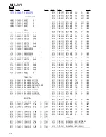
R17

1-249-429-11 CARBON

10K

5%

1/4W

(AEP,UK,HK,AUS)

R21

1-249-429-11 CARBON

10K

5%

1/4W

R22

1-249-429-11 CARBON

10K

5%

1/4W

R23

1-249-429-11 CARBON

10K

5%

1/4W

R28

1-249-429-11 CARBON

10K

5%

1/4W

R41

1-249-441-11 CARBON

100K

5%

1/4W

R44

1-249-429-11 CARBON

10K

5%

1/4W

R46

1-249-429-11 CARBON

10K

5%

1/4W

R49

1-249-429-11 CARBON

10K

5%

1/4W

R51

1-249-429-11 CARBON

10K

5%

1/4W

R53

1-249-429-11 CARBON

10K

5%

1/4W

R55

1-249-429-11 CARBON

10K

5%

1/4W

R61

1-249-429-11 CARBON

10K

5%

1/4W

R87

1-249-429-11 CARBON

10K

5%

1/4W

R88

1-249-429-11 CARBON

10K

5%

1/4W

R90

1-249-441-11 CARBON

100K

5%

1/4W

(AEP,UK,HK,AUS)

R92

1-249-429-11 CARBON

10K

5%

1/4W

R93

1-249-429-11 CARBON

10K

5%

1/4W

R94

1-249-429-11 CARBON

10K

5%

1/4W

R95

1-249-429-11 CARBON

10K

5%

1/4W

R97

1-249-429-11 CARBON

10K

5%

1/4W

R100

1-249-441-11 CARBON

100K

5%

1/4W

R111

1-249-435-11 CARBON

33K

5%

1/4W

R112

1-249-431-11 CARBON

15K

5%

1/4W

R113

1-247-887-00 CARBON

220K

5%

1/4W

R115

1-249-401-11 CARBON

47

5%

1/4W F

R161

1-215-445-00 METAL

10K

1%

1/4W

R162

1-215-445-00 METAL

10K

1%

1/4W

R163

1-215-445-00 METAL

10K

1%

1/4W

R164

1-215-445-00 METAL

10K

1%

1/4W

R165

1-215-453-00 METAL

22K

1%

1/4W

R166

1-215-453-00 METAL

22K

1%

1/4W

R171

1-215-425-00 METAL

1.5K

1%

1/4W

R172

1-215-425-00 METAL

1.5K

1%

1/4W

R176

1-249-415-11 CARBON

680

5%

1/4W F

R177

1-249-441-11 CARBON

100K

5%

1/4W

R178

1-249-411-11 CARBON

330

5%

1/4W

R181

1-249-429-11 CARBON

10K

5%

1/4W

(AEP,UK,HK,AUS)

R211

1-249-435-11 CARBON

33K

5%

1/4W

R212

1-249-431-11 CARBON

15K

5%

1/4W

R213

1-247-887-00 CARBON

220K

5%

1/4W

R215

1-249-401-11 CARBON

47

5%

1/4W F

R261

1-215-445-00 METAL

10K

1%

1/4W

R262

1-215-445-00 METAL

10K

1%

1/4W

R263

1-215-445-00 METAL

10K

1%

1/4W

R264

1-215-445-00 METAL

10K

1%

1/4W

R265

1-215-453-00 METAL

22K

1%

1/4W

R266

1-215-453-00 METAL

22K

1%

1/4W

R271

1-215-425-00 METAL

1.5K

1%

1/4W

R272

1-215-425-00 METAL

1.5K

1%

1/4W

R276

1-249-415-11 CARBON

680

5%

1/4W F

R277

1-249-441-11 CARBON

100K

5%

1/4W

R278

1-249-411-11 CARBON

330

5%

1/4W

R281

1-249-429-11 CARBON

10K

5%

1/4W

(AEP,UK,HK,AUS)

R380

1-249-441-11 CARBON

100K

5%

1/4W

R381

1-247-883-00 CARBON

150K

5%

1/4W

R406

1-249-409-11 CARBON

220

5%

1/4W F

R407

1-249-429-11 CARBON

10K

5%

1/4W

R422

1-247-881-00 CARBON

120K

5%

1/4W

R423

1-249-441-11 CARBON

100K

5%

1/4W

R424

1-249-409-11 CARBON

220

5%

1/4W F

R425

1-249-409-11 CARBON

220

5%

1/4W F

R431

1-247-807-31 CARBON

100

5%

1/4W

R432

1-249-415-11 CARBON

680

5%

1/4W F

R433

1-249-411-11 CARBON

330

5%

1/4W

R434

1-249-433-11 CARBON

22K

5%

1/4W

R435

1-249-438-11 CARBON

56K

5%

1/4W

R436

1-247-891-00 CARBON

330K

5%

1/4W

R437

1-249-417-11 CARBON

1K

5%

1/4W F

R441

1-249-433-11 CARBON

22K

5%

1/4W

R442

1-249-431-11 CARBON

15K

5%

1/4W

R443

1-249-433-11 CARBON

22K

5%

1/4W

R491

1-249-411-11 CARBON

330

5%

1/4W

R492

1-249-418-11 CARBON

1.2K

5%

1/4W F

R511

1-249-401-11 CARBON

47

5%

1/4W F

R512

1-249-401-11 CARBON

47

5%

1/4W F

Summary of Contents for MDS-JE470 - Md Player

Page 1: ...CLV 400 rpm to 900 rpm Error correction ACIRC Advanced Cross Interleave Reed Solomon Code Sampling frequency 44 1 kHz Coding ATRAC Adaptive TRansform Acoustic Coding ATRAC 3 Modulation system EFM Eight to Fourteen Modulation Number of channels 2 stereo channels Frequency response 5 to 20 000 Hz 0 3 dB Signal to noise ratio Over 96 dB during play Wow and flutter Below measurable limit Inputs ANALOG...

Page 2: ...e The inserted MD is dirty with smudges fingerprints etc scratched or substandard in quality Replace the disc and repeat the recording procedure C13 Read Error The deck could not read the TOC on the MD properly Take out the MD and insert it again C14 Toc Error The deck could not read the TOC on the MD properly Insert another disc If possible erase all the tracks on the MD C41 Cannot Copy The sound...

Page 3: ...address histories Procedure 1 Press the lAMSL knob when displayed as er refresh 2 Press the YES button when the display changes to er refresh When complete is displayed it means erasure has completed Be sure to check the following after executing this mode Data has been erased Perform recording and playback and check that the mechanism is normal Mode for erasing the total time of recording and pla...

Page 4: ...nob when displayed as spdl change 2 Press the YES button when the display changes to spdl change When Complete is displayed it means erasure has completed TABLE OF CONTENTS 1 SERVICING NOTES 5 2 GENERAL 12 3 DISASSEMBLY 3 1 Disassembly flow 13 3 2 Upper Case 408226 14 3 3 Front Panel Section 14 3 4 Main Board 15 3 5 PT Board VOL SEL Board SP model 15 3 6 Mechanism Deck Section MDM 7A 16 3 7 Over L...

Page 5: ...TICAL TO SAFE OPERATION REPLACE THESE COMPONENTS WITH SONY PARTS WHOSE PART NUMBERS APPEAR AS SHOWN IN THIS MANUAL OR IN SUPPLEMENTS PUBLISHED BY SONY ATTENTION AU COMPOSANT AYANT RAPPORT À LA SÉCURITÉ LES COMPOSANTS IDENTIFÉS PAR UNE MARQUE 0 SUR LES DIAGRAMMES SCHÉMATIQUES ET LA LISTE DES PIÈCES SONT CRITIQUES POUR LA SÉCURITÉ DE FONCTIONNEMENT NE REMPLACER CES COMPOSANTS QUE PAR DES PIÈSES SONY...

Page 6: ... as follows GND Ground I 3V For measuring IOP Check the deterioration of the optical pick up laser IOP For measuring IOP Check the deterioration of the optical pick up laser TE TRK error signal Traverse adjustment VC Reference level for checking the signal RF RF signal Check jitter FE Focus error signal I 3V Iop GND TE FE VC RF I 3V IOP GND TE FE VC RF 1 7 for MDM 7A I 3V CN105 IOP TE VC GND FE RF...

Page 7: ...an be changed will blink 5 Input the Iop value written on the optical pick up To select the number Rotate the l AMS L knob To select the digit Press the l AMS L knob 6 When the YES button is pressed the display becomes Measu is an arbitrary number 7 As the adjustment results are recorded for the 6 value Leave it as it is and press the YES button 8 Complete will be displayed momentarily The value w...

Page 8: ...r of the adhesive agent at PDIC portion Pink White Form of FPC retainer plate Close the hole on SL base Not close the hole on SL base APC variable resistor Small volume 2 type Big variable resistor 3 type and chip resistor Fig A Small variable resistor 2 type and chip resistor Fig B Fig B type is for repair Abbreviation 260B KMS 260B model 260E KMS 260E model KSN 260B KSN 260E Fig A Fig B CHIP 3 t...

Page 9: ...e page 29 Note The criteria for determination above is intended merely to determine if satisfactory or not and does not serve as the specified value for adjustments When performing adjustments use the specified values for adjustments FORCED RESET The system microprocessor can be reset in the following procedure Use these procedure when the unit cannot be operated normally due to the overrunning of...

Page 10: ...L DISPLAY CHAR button while pressing the x button and MENU NO button 7 When the mode is set RTs 00c 00e 000 is displayed 8 Press the z REC button to start recording Then press the X button and start recording 9 To check the track mode press the H button to start play 10 To exit the test mode press the 1 button and turn OFF the power When TOC disappears disconnect the power plug from the outlet If ...

Page 11: ...ause is combined of emphasis OFF monaural original copyright exists and write allowed Example When 07 is displayed Higher bit 0 1000 t All 0 Lower bit 7 0111 t b0 b1 b2 In this case as b0 b1 and b2 are 1 and others are 0 it can be determined that the retry cause is combined of emphasis ON stereo original copyright exists and write prohibited Hexadecimal t Binary Conversion Table Hexadecimal Binary...

Page 12: ...a wd wg AMS wh wa 8 3 4 ws w qj 1 9 qh qg qk ws wf 2 ql 1 5 qf qd 6 7 qs A z 1 H 0 X qa x wd m M wg 15 20 25 35 39 CLEAR 23 30 40 Display window EJECT 11 20 25 GROUP ON OFF1 13 22 31 GROUP SKIP1 13 22 31 INPUT 11 LEVEL DISPLAY CHAR 11 21 29 MD insertion slot MDLP indicator 14 21 MENU NO 15 22 25 35 39 PC LINK KEYBOARD 1 39 PHONE LEVEL1 21 PHONES jack1 17 21 36 PLAY MODE 20 37 REC MODE 14 22 REC 11...

Page 13: ...del 3 6 MECHANISM DECK SECTION MDM 7A 3 7 OVER LIGHT HEAD HR901 3 11 OPTICAL PICK UP KMS 260B 260E 3 7 BD BOARD 3 8 HOLDER ASSY 3 9 LOADING MOTOR ASSY M103 3 10 SLED MOTOR ASSY M102 3 12 SPINDLE MOTOR ASSY M101 3 7 BD BOARD 3 8 HOLDER ASSY Abbreviation SP Singapore Note 1 The processes enclosed with remove in the any order Note 2 You cannot go to the next process until every process enclosed with ...

Page 14: ... 1 Two screws CASE 3TP2 1 Two screws CASE 3TP2 1 Screw CASE 3TP2 2 Case 408226 3 3 FRONT PANEL SECTION 4 Two screws BVTP3x8 4 Two screws BVTP3x8 6 Front panel 5 Claw 5 Claw 1 Wire flat type 17core CN3 2 Connector CN390 3 Connector CN830 ...

Page 15: ...3x8 4 Two screws BVTP3x8 5 screw BVTP3x8 3 Connector CN400 2 Wire flat type 23core CN1 1 Wire flat type 27core CN2 7 MAIN board 6 Two screws BVTP3x8 SP model 3 Three screws PTTWH M3 2 Connector CN990 SP model 1 Connector CN900 5 PT board 7 VOL SEL board SP model 4 Nylom rivet dia 3 ...

Page 16: ...d over light HP901 4 Remove the solder four portion 4 Remove the solder five portion 5 Two screws BTP2X6 7 FLEXIBLE board CN101 8 BD board 1 Connector CN104 2 Screw P1 7X6 Note 1 If you disconnect the connector CN104 you can remove the BD board without removing the over write head HR901 Note 2 Be careful to handle the over write head HR901 because it is easy to be damaged ...

Page 17: ...17 MDS JE470 3 8 HOLDER ASSY 3 9 LOADING MOTOR ASSY M103 5 3 6 Holder ASSY 2 Claw 4 Boss 4 Boss 1 Spring holder tension 2 Two screws PWH1 7x2 5 3 Motor ASSY loading M103 1 Belt loading ...

Page 18: ... Slider 8 Lever head 4 Slider EJ 5 Remove the claw Shift the slider in the arrow direction 1 FLEXIBLE board qa Optical pick up KMS 260B 260E 7 Main shaft 6 Two screws K2X6 4 Screw BTP2X6 5 Base BU A 3 Gear SD 2 Screw M1 7 tapping 0 SL base 9 Screw P1 7X6 8 3 10 SLED MOTOR ASSY M102 SLIDER 3 11 OPTICAL PICK UP ...

Page 19: ...19 MDS JE470 2 Spindle motor ASSY M101 1 Three screws M1 7 tapping 3 12 SPINDLE MOTER ASSY M101 ...

Page 20: ...djustment EF MO ADJUS C07 When pressing the z REC button 4 2 SETTING THE TEST MODE The following are two methods of entering the test mode Procedure 1 While pressing the lAMS L knob and x button connect the power plug to an outlet and release the lAMS L knob and x button When the test mode is set Check will be displayed Rotating the l AMS L knob switches between the following three groups y Check ...

Page 21: ...etc Continuous playback mode Continuous recording mode 4 5 SELECTING THE TEST MODE There are 26 types of test modes as shown below The groups can be switched by rotating the l AMS L knob After selecting the group to be used press the YES button After setting a certain group rotating the l AMS L knob switches between these modes Refer to Group in the table for details selected All adjustments and c...

Page 22: ... the Continuous Recording Mode Use only when performing self recording palyback check 1 Entering the continuous recording mode 1 Set a recordable disc in the unit 2 Rotate the l AMS L knob and display CREC1 MODE C35 3 Press the YES button to change the display to CREC1 MID 4 When access completes the display changes to CREC 1 and REC lights up Note The numbers displayed shows you the recording pos...

Page 23: ...es in the following order When CPLAY and CREC are started the display will forcibly be switched to the error rate display as the initial mode 1 Mode display Displays TEMP ADJUST CPLAY1MODE etc 2 Error rate display Displays the error rate in the following way C AD C Indicates the C error AD Indicates ADER 3 Address display The address is displayed as follows MO recordable disc CD playback only disc...

Page 24: ... displayed Load the check disc MD TDYS 1 5 When the disc is loaded in step 4 the check will automatically be resumed from 07 CHECK 6 After completing to test item 12 check OK or NG will be displayed If all items are OK CHECKALL OK will be displayed If any item is NG it will be displayed as NG xxxx When CHECK ALL OK is displayed it means that the optical pick up is normal Check the operations of th...

Page 25: ... as sound skipping are suspected follow the following check Check before replacement Other faults are suspected Check the threading mechanism etc Start NG NG NG OK OK OK Laser Power Check 5 6 2 See page 28 5 6 3 See page 28 5 6 4 See page 29 Iop Compare Auto Check Replace Optical pick up or MDM 7A Note 260B KMS 260B 260E KMS 260E ...

Page 26: ...ts After turning off and then on the power initialize the EEPROM For details refer to 4 11 WHEN MEMORY NG IS DISPLAYED See page 24 Abbreviation OP Optical pick up 5 7 INITIAL SETTING OF ADJUSTMENT VALUE See page 31 5 9 TEMPERATURE COMPENSATION OFFSET ADJUSTMENT See page 31 5 10 LASER POWER ADJUSTMENT See page 31 5 12 TRAVERSE ADJUSTMENT See page 32 5 13 FOCUS BIAS ADJUSTMENT See page 33 5 16 AUTO ...

Page 27: ...tments and checks with in the order shown in the following table 2 Set the test mode when performing adjustments After completing the adjustments exit the test mode Perform the adjustments and checks in group S of the test mode 3 Perform the adjustments to be needed in the order shown 4 Use the following tools and measuring devices Check Disc MD TDYS 1 Parts No 4 963 646 01 Test Disk MDW 74 GA 1 P...

Page 28: ...t and indicates the value written in the non volatile memory 5 6 2 Laser Power Check Before checking check the Iop value of the optical pick up Refer to 5 8 Recording and Displaying Iop Information Connection KMS 260B 20101 H0576 Iop 57 6 mA in this case Iop mA Digital voltmeter reading mV 1 Ω Checking Procedure 1 Set the laser power meter on the objective lens of the optical pick up When it canno...

Page 29: ...erform this test mode the laser power must first be checked Perform Auto Check after the laser power check and Iop compare Procedure 1 Press the YES button If LDPWR minicheck is displayed it means that the laser power check has not been performed In this case perform the laser power check and Iop compare and then repeat from step 1 2 If a disc is in the mechanical deck it will be ejected forcibly ...

Page 30: ...elow 2 10 Press the MENU NO button to stop playback and press the A EJECT button and remove the disc 5 6 7 Focus Bias Check Change the focus bias and check the focus tolerance amount Checking Procedure 1 Load a continuously recorded test disc MDW 74 GA 1 Refer to 5 5 Using the Continuously Recorded Disc 2 Rotate the l AMS L knob and display CPLAY1 MODE 3 Press the YES button and display CPLAY1 MID...

Page 31: ...r adjustment 3 To end press the l AMS L button or MENU NO button to display Iop Read 5 9 TEMPERATURE COMPENSATION OFFSET ADJUTMENT Save the temperature data at that time in the non volatile memory as 25 C reference data Note 1 Usually do not perform this adjustment 2 Perform this adjustment in an ambient temperature of 22 C to 28 C Perform it immediately after the power is turned on when the inter...

Page 32: ...e specified value When the l AMS L knob is rotated the of EFB changes and the waveform changes In this adjustment waveform varies at intervals of approx 2 Adjust the wave form so that the specified value is satisfied as much as possible Read power traverse adjustment Traverse Waveform 7 Press the YES button and save the result of adjustment to the non volatile memory EFB SAVE will be displayed for...

Page 33: ...it can be seen more clearly 5 13 FOCUS BIAS ADJUSTMENT Adjusting Procedure 1 Load a test disk MDW 74 GA 1 2 Rotate the l AMS L knob and display CPLAY1 MODE 3 Press the YES button and display CPLAY1 MID 4 Press the MENU NO button when C AD is displayed 5 Rotate the l AMS L knob and display FBIAS AD JUST 6 Press the YES button and display a The first four digits indicate the C error rate the two dig...

Page 34: ...low 2 7 Press the YES button and display b Check that the C error is below 100 and ADER is below 2 8 Press the YES button and display a Check that the C error is below 100 and ADER is below 2 9 Press the MENU NO button next press the A EJECT button and remove the continuously recorded disc Note 1 If the C error and ADER are above other than the speci fied value at points a step 8 in the above or b...

Page 35: ...l to use the jig for checking the waveform Refer to Servicing Note on page 6 BD BOARD SIDE B D101 IC151 23 1 27 1 1 7 IC101 CN101 CN103 CN102 IC195 IC190 CN105 IC102 NOTE 5 17 ADJUSTING POINTS AND CONNECTING POINTS BD BOARD SIDE A ...

Page 36: ...36 MDS JE470 SECTION 6 DIAGRAMS 6 1 CIRCUIT BOARDS LOCATION KEY SW board DISPLAY board BD board MAIN board PT board VOL SEL board SP model Abbreviation SP Singapore model ...

Page 37: ...ith a oscilloscope Voltage variations may be noted due to normal produc tion tolerances Circled numbers refer to waveforms Signal path E PB j REC p PB DIGITAL OUT l REC DIGITAL IN Abbreviation CND Canadian model SP Singapore model HK Hong Kong model AUS Australian model Caution Pattern face side Parts on the pattern face side seen from the Side B pattern face are indicated Parts face side Parts on...

Page 38: ...40 M103 LOADING DQ1 DQ4 A0 A9 D0 D3 A00 A09 XOE XWE XRAS XCAS OE WE RAS CAS D RAM IC153 DIN1 SYSTEM CONTROLLER IC1 1 2 HF MODULE ADDT DADT BCK LRCK SWDT SCLK REFLECT PROTECT LD LOW SDA SCL UNREG 12V 65 LIMIT IN OUT SW S101 LIMIT IN PLAY SW SIGNAL PATH PLAY ANALOG OUT REC ANALOG IN REC DIGITAL IN S103 OUT SW S104 PLAY SW REC SW S105 REC POSITION XBCKI LRCKI S102 REFLECT PROTECT DETECT HIGH REFELECT...

Page 39: ...TER INTERFACE BICK LRCK A1 OUT A1 IN DADT BCK LRCK AINL AINR XTI FLDT FLCK FLCS JOG0 GND SW JOG1 P DOWN l AMS L PUSH ENTER S713 S701 706 711 712 S714 716 721 724 S726 A B SWDT SCLK CDTI CCLK CS PD SIRCS OSCI C769 R769 OSCO MIX AMP IC360 1 2 MIX AMP IC360 2 2 OSC IC550 LOW PASS FILTER IC370 1 2 LOW PASS FILTER IC370 2 2 D C SWDT SCLK 1024FS Page38 Page38 Page38 Page38 SIGNAL PATH RST XIN XOUT X15 1...

Page 40: ... D 3 D183 D 3 IC101 A 3 IC102 B 3 IC141 C 1 IC151 C 2 IC153 C 3 IC171 D 2 Semiconductor Location Ref No Location IC181 D 3 IC190 D 1 IC195 D 2 Q121 B 3 Q122 B 3 Q181 D 3 Q182 D 3 6 3 PRINTED WIRING BOARD BD Board See page 36 for Circuit Board Location There are a few cases that the part isn t mounted in model is printed on diagram BD BOARD SIDE A OPTICAL PICK UP HR901 OVER WRITE HEAD BLOCK KMS 260...

Page 41: ...41 41 6 4 SCHEMATIC DIAGRAM BD SECTION 1 2 See page 37 for Waveforms See page 52 for IC Pin Functions See page 50 for IC Block Diagrams KMS 260B 260E BD BOARD 2 2 Page 42 BD BOARD 2 2 Page 42 BD BOARD 2 2 Page 42 ...

Page 42: ...DIAGRAM BD SECTION 2 2 See page 37 for Waveforms See page 53 for IC Pin Functions See page 50 for IC Block Diagrams MAIN BOARD 1 2 CN2 Page 43 MAIN BOARD 1 2 CN1 Page 43 BD BOARD 1 2 Page 41 BD BOARD 1 2 Page 41 BD BOARD 1 2 Page 41 ...

Page 43: ...D NJM4558D AK4524 100 10V JUMPER M30803MG 107FP 10k 10k 330 10k TC7WHU04FU TE12R 12p 330 0UH 1SS133T 72 1SS133T 72 1SS133T 72 1SS133T 72 1SS133T 72 1SS133T 72 10k 1 2 3 4 5 6 7 9 8 10 11 12 13 14 15 16 17 18 20 PROTECT PROTECT REFRECT REFRECT SDA SDA SCL SCL EEP WP EEP WP SHOCK SHOCK XBUSY XBUSY SWDT SWDT SRDT SRDT OUT SW OUT SW SCLK SCLK XLATCH XLATCH PLAY SW PLAY SW SENS SENS DIG RST DIG RST REC...

Page 44: ...01 10000 16V 10000 16V 0 33 50V 1000 6 3V 100 63V 47 50V 33 25V 22 25V JUMPER 100 47k 2 2k 100 16V 22k 22k 15k 220 JUMPER JUMPER 100 10V JW 100k 11ES2 NTA2 2SD2144S TP UVW 11EQS04 11EQS04 11EQS04 11EQS04 11ES2 NTA2B 11ES2 NTA2B 11ES2 NTA2B 11ES2 NTA2B 11ES2 NTA2B 11ES2 NTA2B M62016L M5F7805L 2P ML1220 M5293L BA033T RD4 7EB2 M54641L 2SA1175 HFE 11EQS04 11EQS04 UN4211 TA 1SS133T 72 1SS133T 72 1SS133...

Page 45: ...172 R272 R171 R271 C361 1 4 8 5 1 4 8 5 1 4 8 5 C366 C166 C266 R166 R266 R165 R265 C165 C265 R163 R164 R264 R263 R161 R261 R162 R262 JW251 C161 C261 J800 Q490 E JW162 C113 C213 R115 R215 D112 JW114 C100 C550 JW143 R515 JW247 JW217 JW194 C519 R517 JW180 C515 JW140 R514 JW192 JW195 C657 JW201 L651 R516 L552 JW193 C516 R513 JW104 R511 C523 C501 C500 JW103 R381 R512 L555 JW177 C551 JW183 C552 C555 C55...

Page 46: ...R763 JW789 C760 C761 C762 C763 C769 R769 C751 JW788 Q775 E 1 4 C782 C781 JW784 C753 R782 JW786 JW796 JW781 JW795 CN701 1 2 15 14 LP709 JW798 JW799 C766 Q767 E JW791 C765 R781 R775 JW792 LP719 JW811 JW802 C767 JW801 R705 R704 JW804 R702 R712 R706 R703 JW805 JW809 JW807 JW808 R767 CN710 JW803 C709 JW752 R722 JW751 R726 R725 R1726 Q726 JW750 C740 AEP AUS HK SP UK R723 R724 CN720 S722 PLAY MODE S723 R...

Page 47: ...EL5821A TP15 MSM9202 07GS K UN4216 ENCODER 100 10V 4P 100 100 100 100 0 1 0 1 S1 S2 S3 S4 S5 S6 S7 S8 S9 S10 S11 S12 S13 S14 S15 S16 S17 S18 S19 S20 S21 S22 S23 S24 S25 S26 S27 S28 S29 S30 S31 S32 S33 S34 S35 G1 G2 G3 G4 G5 G6 G7 G8 G9 G10 G11 G12 G1 G2 G3 G4 S1 S2 S3 S4 S5 S6 S7 S8 S9 S10 S11 S12 S13 S14 S15 S16 S17 S18 S19 S20 S21 S22 S23 S24 S25 S26 S27 S28 G5 G6 G7 G8 G9 G10 G11 G12 G13 S29 S3...

Page 48: ... BOARD 12 12 1 681 734 MAIN BOARD CN400 Page45 F AC IN VOLTAGE SELECT 115V 230V 12 12 1 681 738 NOT REPLACEABLE BUILT IN TRANSFORMER CHASSIS 2 3 4 5 6 7 8 9 A 1 B C D E C910 RY910 LF900 JW903 CN950 D910 JW904 C952 C924 JW901 CN900 LP900 C923 EP900 JW902 TR950 TR900 C951 CN921 WIRE 10P 1 1 1 2 2 2 3 3 4 4 6 8 4 5 5 12 10 8 6 13 11 9 7 1 2 3 4 5 S990 S990 CN990 SP SP EXCEPT SP EXCEPT SP 1 5 11 ...

Page 49: ...JW901 JW902 C910 RY910 LF900 CN921 EP900 CN990 CN950 S990 JW903 D910 2P JUMPER 0 1 0 1 0 1 0 1 0 0022 RELAY LINE FILTER EARTH PLATE 5P WIRE 5P 1SS133 72 AC IN 1 5 11 115V 230V VOLTAGE SELECTOR BUILT IN TRANSFORMER NOT REPLACEABLE POWER TRANSFORMER CHASSIS EXCEPT SP SP SP MAIN CN400 BOARD 2 2 Page49 ...

Page 50: ...LPT PTGR 2 1 1 2 BOTTOM PEAK RF AGC EQ EQ DET P P WBL 3T WBL TEMP PBH USROP USRC 3T BPF3T PEAK3T 1 I 2 J RFA3 PBSW AUX SW IV ESW EBAL 100 99 98 97 96 95 94 93 EFMO DVSS TEST3 TEST2 TEST1 FGIN SPFD SPRD 92 SFDR 91 SRDR 90 FS4 89 FRDR 88 FFDR 87 DVDD 86 TFDR 85 TRDR 84 TEST0 83 APCREF 82 DTRF 81 CKRF 80 XLRF 79 F0CNT 78 ADFG 77 TEST4 76 DCHG 75 TE 74 SE 73 AVSS 72 ADRB 71 ADRT 70 AVDD 69 ADIO 62 CLT...

Page 51: ...R AUDIO INTERFACE CONTROLLER CDTI 15 CIF 18 CLKO 21 AOUTL 26 AOUTL 25 DGND 24 VD 23 VT 22 AOUTR 28 AOUTR 27 PD 19 M S 20 CS 17 CCLK 16 CONTROL REGISTER INTERFACE H P F D ATT D ATT S MUTE REG CONTROL INPUT AMP INPUT AMP 1 2 3 4 5 6 7 8 POWER AMP POWER AMP VCC OUT1 IN2 VZ GND IN1 OUT2 VCC IC421 M5293L MAIN BOARD 2 5 5k 27k OVERCURRENT LIMITTER OVERHEAT PROTECTION REFERENCE VOLTAGE GND ON OFF VIN REF...

Page 52: ... 3V power supply Center frequency setting pin for the internal circuit BPF22 Tracking error signal output to the CXD2662R External capacitor connection pin for the sled error signal LPF Sled error signal output to the CXD2662R FM signal output of ADIP ADIP signal comparator input ADFM is connected with AC coupling External capacitor connection pin for AGC of ADIP ADIP duplex signal output to the C...

Page 53: ... 13 3 msec Almost all H is output Digital In U bit CD format or MD format subcode Q sync SCOR output to the system control Laser power switching input from the system control H Recording L Playback Interrupt status output to the system control Recording data output enable input from the system control System clock input 512Fs 22 5792 MHz System clock output 512Fs 22 5792 MHz Not used System clock ...

Page 54: ... bottom hold input from the CXA2523AR Light amount signal input from the CXA2523AR Focus error signal input from the CXA2523AR Auxiliary A D input Middle point voltage 1 5V input from the CXA2523AR Monitor output of the A D converter input signal Not used 3V power supply Analog A D converter operational range upper limit voltage input Fixed at H A D converter operational range lower limit voltage ...

Page 55: ...O Tracking servo drive PWM output 3V power supply Digital Focus servo drive PWM output Focus servo drive PWM output 176 4 kHz clock signal output X tal Not used Sled servo drive PWM output Sled servo drive PWM output Spindle servo drive PWM output Spindle servo drive PWM output Test input Fixed at L Ground Digital EFM output when recording Abbreviation EFM Eight to Fourteen Modulation ...

Page 56: ...back system 21 KB CLK I Keyboard clock input Fixed at H 22 KB DATA I Keyboard data input Fixed at H 23 IIC BUSY I IIC cable connect check L Active 24 A1 OUT O Not used open 25 XINIT I Interrupt status input from CXD2662R 26 BEEP O Not used open 27 LRCKI O Not used open 28 IIC POWER O Media commucator start up check 29 IIC CLK O IIC serial clock output 30 IIC DATA I O IIC serial data input output 3...

Page 57: ...REC SW I Detection signal input from the recording position detection switch L REC 54 WR PWR O Write power ON OFF output L OFF H ON 55 LIMIT IN I Detection input from the limit switch L Sled limit In H Sled limit Out 56 MOD O Laser modulation switching signal output L STOP H PLAY pluse REC 57 LDON O Laser ON OFF control output H Laser ON 58 SENS I Internal status SENSE input from the CXD2662R 59 S...

Page 58: ...ulse input from the rotary encoder 89 IOP I Optical Pick up voltage current detect signal input 90 DISTINATION I Model discrimination 91 MODEL SEL I Model discrimination 92 TIMER I Not used Fixed at H 93 KEY3 I Not used Fixed at H 94 95 KEY2 1 I Key input pin A D input 96 AVSS Ground Analog 97 KEY0 I Key input pin A D input 98 VREF I A D reference voltage 99 AVCC I Power supply 3 3V 100 NC I Not u...

Page 59: ...ied 1 1 1 1 1 1 1 1 1 1 1 7 4 7 6 5 6 11 12 17 17 SP UK HK 13 14 15 15 16 15 3 2 1 Front panel section 8 18 2 1 1 X 4953 448 1 FOOT ASSY 2 4 232 237 01 FOOT DIA 30 3 4 233 025 01 PANEL BACK AEP UK 3 4 233 025 11 PANEL BACK US 3 4 233 025 21 PANEL BACK CND 3 4 233 025 31 PANEL BACK SP 3 4 233 025 41 PANEL BACK HK 3 4 233 025 51 PANEL BACK AUS 4 9 910 999 31 RIVET DIA 3 NYLON 5 1 681 734 12 PT BOARD...

Page 60: ...4 951 620 01 SCREW 2 6X8 BVTP 56 4 228 630 01 SPRING LID TENSION COIL 57 4 228 629 81 LID MD BLACK 57 4 230 848 21 LID MD SILVER 59 1 681 737 12 KEY SW BOARD 60 A 2007 907 A DISPLAY BOARD COMPLETE US CND 60 A 2007 911 A DISPLAY BOARD COMPLETE AEP UK HK AUS 60 A 2007 915 A DISPLAY BOARD COMPLETE SP 61 4 949 935 41 CUSHION FL 62 4 212 590 01 HOLDER FL 63 1 757 930 11 WIRE FLAT TYPE 17 CORE 64 4 231 ...

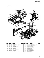
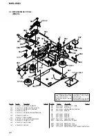
Page 61: ...ELT LOADING 305 3 372 761 01 SCREW M1 7 TAPPING 306 4 227 002 01 GEAR PULLEY 307 4 226 999 01 LEVER HEAD 308 X 4952 665 1 SPRING SHT ASSY LEAF 309 A 4672 990 F LOCK HOLDER 310 4 229 533 01 SPRING STOPPER TORSION 311 4 231 118 01 SPRING HOLDER TENSION 312 4 227 019 02 PLATE HOLDER ASSY RETAINER 313 4 227 013 01 SPRING EJ TENSION 314 4 226 995 01 SLIDER EJ 315 4 226 996 01 LIMITTER EJ 316 4 226 997 ...

Page 62: ... BD BOARD COMPLETE 352 4 231 319 01 SCREW 2X6 CZN B P TRI 353 3 372 761 01 SCREW M1 7 TAPPING 354 4 226 993 01 RACK 355 4 227 014 01 SPRING RACK COMPRESSION 356 4 226 992 01 BASE SL 357 1 678 514 11 PWB FLEXIBLE 0358 A 4672 541 A OPTICAL PICK UP KMS 260E 359 4 988 560 01 SCREW P 1 7X6 360 4 996 265 01 SHAFT MAIN 361 4 226 989 01 CHASSIS 362 4 232 270 01 SCREW 1 7X3 5 PWH 363 4 226 990 01 BASE BU A...

Page 63: ...17 720 11 CERAMIC CHIP 4 7uF 10V C128 1 164 156 11 CERAMIC CHIP 0 1uF 25V C131 1 117 720 11 CERAMIC CHIP 4 7uF 10V C132 1 164 156 11 CERAMIC CHIP 0 1uF 25V C133 1 164 156 11 CERAMIC CHIP 0 1uF 25V C141 1 126 206 11 ELECT CHIP 100uF 20 6 3V C142 1 164 156 11 CERAMIC CHIP 0 1uF 25V C143 1 164 156 11 CERAMIC CHIP 0 1uF 25V C144 1 162 970 11 CERAMIC CHIP 0 01uF 10 25V C145 1 164 156 11 CERAMIC CHIP 0 ...

Page 64: ...1 218 855 11 METAL CHIP 2 2K 0 5 1 16W R119 1 218 863 11 METAL CHIP 4 7K 0 5 1 16W R120 1 218 889 11 METAL CHIP 56K 0 5 1 16W R121 1 218 863 11 METAL CHIP 4 7K 0 5 1 16W R122 1 218 855 11 METAL CHIP 2 2K 0 5 1 16W R123 1 216 819 11 METAL CHIP 680 5 1 16W R124 1 216 809 11 METAL CHIP 100 5 1 16W R125 1 216 815 11 METAL CHIP 330 5 1 16W R126 1 216 819 11 METAL CHIP 680 5 1 16W R127 1 216 845 11 META...

Page 65: ...1 247 807 31 CARBON 100 5 1 4W R761 1 247 807 31 CARBON 100 5 1 4W R762 1 247 807 31 CARBON 100 5 1 4W R763 1 247 807 31 CARBON 100 5 1 4W R767 1 249 441 11 CARBON 100K 5 1 4W R769 1 247 843 11 CARBON 3 3K 5 1 4W R775 1 249 409 11 CARBON 220 5 1 4W F R781 1 249 401 11 CARBON 47 5 1 4W F R782 1 247 807 31 CARBON 100 5 1 4W SWITCH S701 1 762 875 21 SWITCH KEYBOARD REC z S702 1 762 875 21 SWITCH KEYB...

Page 66: ...4 665 11 ELECT 100uF 20 10V C505 1 164 159 11 CERAMIC 0 1uF 50V C515 1 162 282 31 CERAMIC 100PF 10 50V C516 1 162 282 31 CERAMIC 100PF 10 50V C517 1 162 282 31 CERAMIC 100PF 10 50V C519 1 162 294 31 CERAMIC 0 001uF 10 50V C520 1 126 934 11 ELECT 220uF 20 10V C522 1 164 159 11 CERAMIC 0 1uF 50V C523 1 104 665 11 ELECT 100uF 20 10V C524 1 164 159 11 CERAMIC 0 1uF 50V C530 1 164 159 11 CERAMIC 0 1uF ...

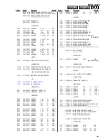
Page 67: ...4W R97 1 249 429 11 CARBON 10K 5 1 4W R100 1 249 441 11 CARBON 100K 5 1 4W R111 1 249 435 11 CARBON 33K 5 1 4W R112 1 249 431 11 CARBON 15K 5 1 4W R113 1 247 887 00 CARBON 220K 5 1 4W R115 1 249 401 11 CARBON 47 5 1 4W F R161 1 215 445 00 METAL 10K 1 1 4W R162 1 215 445 00 METAL 10K 1 1 4W R163 1 215 445 00 METAL 10K 1 1 4W R164 1 215 445 00 METAL 10K 1 1 4W R165 1 215 453 00 METAL 22K 1 1 4W R166...

Page 68: ...TR900 1 435 543 11 TRANSFORMER POWER US CND 0TR900 1 435 544 11 TRANSFORMER POWER AEP UK HK AUS 0TR900 1 435 545 11 TRANSFORMER POWER SP 0TR950 1 437 337 11 TRANSFORMER POWER SP 0TR950 1 437 335 11 TRANSFORMER POWER US CND 0TR950 1 437 336 11 TRANSFORMER POWER AEP UK HK AUS 1 681 738 12 VOL SEL BOARD SP CONNECTOR CN990 1 573 565 11 PIN CONNECTOR 5P SP SWITCH 0S990 1 771 474 11 SWITCH POWER VOLTAGE...

Page 69: ...69 MDS JE470 ...
Page 70: ...STORY Clicking the version allows you to jump to the revised page Also clicking the version at the upper right on the revised page allows you to jump to the next revised page Ver Date Description of Revision 1 0 2001 05 New ...

Reviews: