– 79 –
(1)
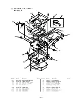
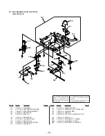
CHASSIS SECTION
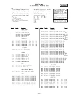
SECTION 5
EXPLODED VIEWS
Les composants identifiés par une
marque
!
sont critiquens pour la
sécurité.
Ne les remplacer que par une pièce
portant le numéro spécifié.
The components identified by
mark
!
or dotted line with mark
!
are critical for safety.
Replace only with part number
specified.
• Items marked “*” are not stocked since they
are seldom required for routine service. Some
delay should be anticipated when ordering
these items.
• The mechanical parts with no reference num-
ber in the exploded views are not supplied.
• Hardware (# mark) list and accessories and
packing materials are given in the last of the
electrical parts list.
NOTE:
• -XX and -X mean standardized parts, so they
may have some difference from the original
one.
• Color Indication of Appearance Parts
Example:
KNOB, BALANCE (WHITE) . . . (RED)
↑
↑
Parts Color Cabinet's Color
Ref. No.
Part No.
Description
Remark
Ref. No.
Part No.
Description
Remark
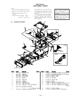
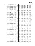
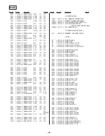
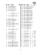
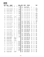
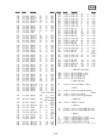
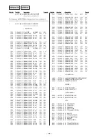
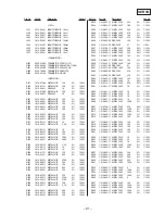
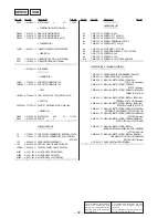
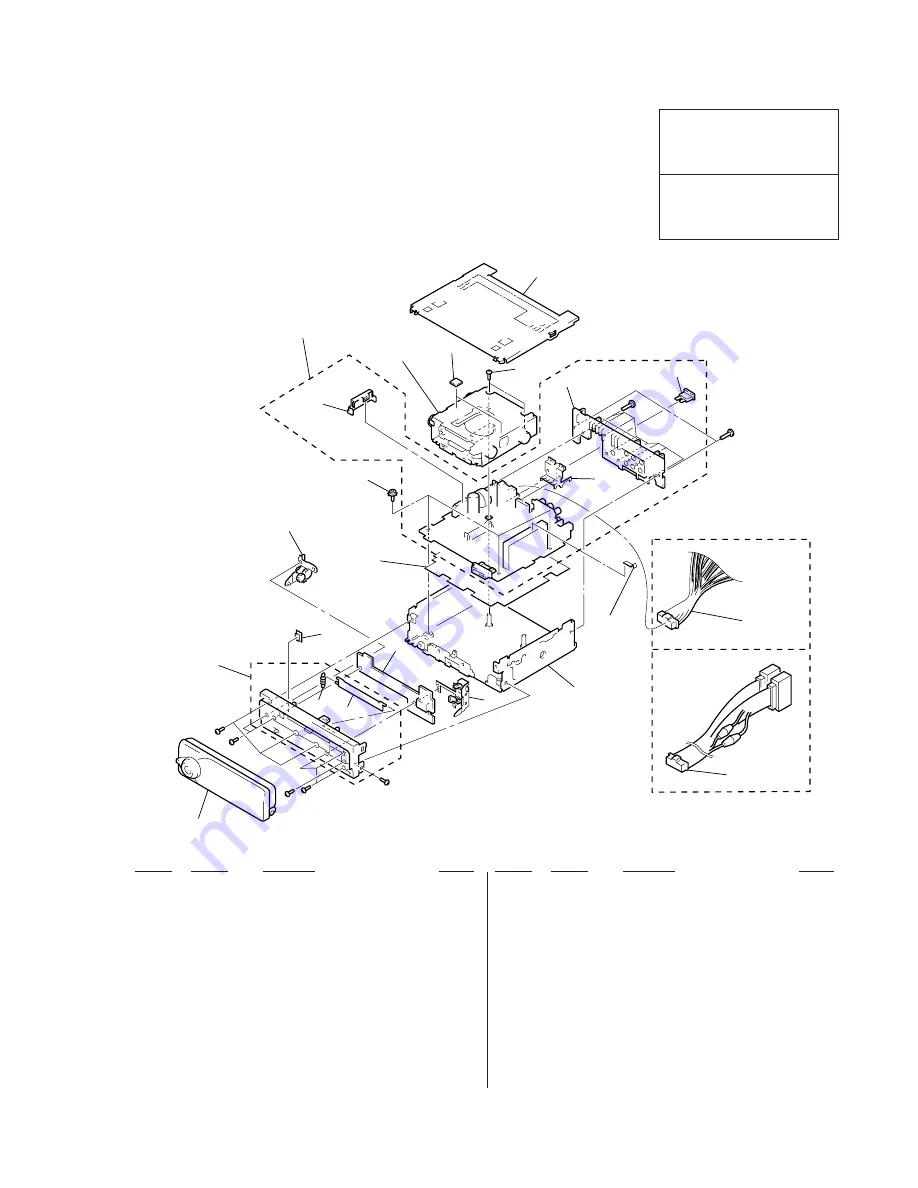
1
X-3376-960-1 PANEL ASSY, SUB
2
3-025-483-01 DOOR (MD)
3
3-025-484-01 SPRING (DOOR)
4
3-022-338-01 BUTTON (EJECT)
5
X-3376-686-1 GEAR ASSY
*
6
1-672-684-11 SUB BOARD
7
X-3376-687-1 LOCK ASSY
*
8
X-3376-959-1 CHASSIS ASSY
*
9
3-033-748-01 SHEET (INSULATING)
10
3-376-464-11 SCREW (+PTT 2.6X6), GROUND POINT
*
11
A-3294-651-A MAIN BOARD, COMPLETE
(C7970: US, Canadian)
*
11
A-3294-657-A MAIN BOARD, COMPLETE (C7970: E)
*
11
A-3294-669-A MAIN BOARD, COMPLETE (C7970R: AEP, UK)
*
11
A-3294-678-A MAIN BOARD, COMPLETE (C7970R: German)
*
12
3-011-078-01 BRACKET (POWER IC)
*
13
3-022-317-01 BRACKET (AMP)
*
14
3-033-716-01 HEAT SINK
15
3-011-999-01 CUSHION (MD)
*
16
3-033-744-01 COVER
17
3-932-860-01 SCREW (2.6X4) (C TIGHT), +PTT
18
1-776-207-72 CORD (WITH CONNECTOR) (POWER) (C7970)
18
1-776-527-71 CORD (WITH CONNECTOR) (ISO) (POWER)
(C7970R)
19
3-360-123-01 PLATE (C), GROUND
F1
1-532-877-11 FUSE (BLADE TYPE) (AUTO FUSE) (10A)
16
11
12
15
17
14
13
10
9
5
4
1
2
3
6
7
8
18
18
F1
#3
#3
MG-164N-138
#2
#1
#4
#1
#2
Front panel section
C7970
C7970R
19
Summary of Contents for MDX-C7970/C7970R
Page 4: ... 4 SECTION 1 GENERAL This section is extracted from instruction manual ...
Page 5: ... 5 ...
Page 6: ... 6 ...
Page 7: ... 7 ...
Page 8: ... 8 ...
Page 9: ... 9 ...
Page 10: ... 10 ...
Page 11: ... 11 ...
Page 41: ... 61 4 20 SCHEMATIC DIAGRAM SUB Board MDX C7970 C7970R Page 54 Page 57 ...
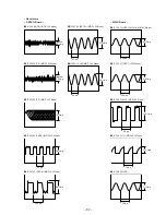
Page 48: ... 68 6 IC700 X1 KEY Board 1 IC801 º OSC IN 5 8 Vp p 271 ns 2 8 Vp p 3 5 µs ...

