57
MDX-M690
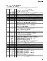
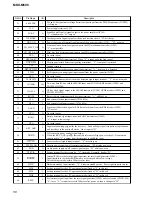
Pin No.
Pin Name
I/O
Description
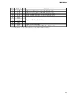
91
VSS
—
Ground terminal
92
X0
I
Main system clock input terminal (3.68 MHz)
93
X1
O
Main system clock output terminal (3.68 MHz)
94
VCC
—
Power supply terminal (+5V)
95
ILL IN
I
Auto dimmer control illumination line detection signal input terminal
“L” is input at dimmer detection
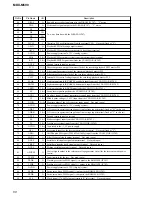
96
I-DET
I
Detection signal input from the motor overload detection circuit for the front panel open/close
motor (M601) “L” is input when the motor current exceeds the specified value
97
MOT–
O
Front panel open/close motor (M601) drive signal (in panel close direction) output to the
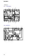
BA6288FS (IC651)
98
MOT+
O
Front panel open/close motor (M601) drive signal (in panel open direction) output to the
BA6288FS (IC651)
99
CLOSE-SW
I
Front panel open/close detection switch input terminal “L” is input when the front panel is
closed
100
OPEN-SW
I
Front panel open/close detection switch input terminal “L” is input when the front panel is
opened
101
CENT-SW
I
Front panel detach position detection switch input terminal “L” is input when the front panel is
detach position
102
NCO
O
Not used (open)
103
CDMD-SEL
I
CD or MD mechanism deck setting terminal “L”: CD, “H”: MD (fixed at “H” in this set)
104, 105
DSTSEL1,
DESTSEL2
I
Destination setting terminal (fixed at “L”)
106
BOOT
O
Serial data output to the display controller (IC702) “L” is output when writing change
107 to 110
NCO
O
Not used (open)
111
PACK-IN
I
Disc insert detection switch input terminal “L” is input when the disc is inserting
112
4V SEL
I
Input terminal of whether line driver is mounted or not is detected
“L”: line driver is mounted (fixed at “H” in this set)
113
NCO
O
Not used (open)
114
TUNER-ON
O
Tuner system power supply on/off control signal output terminal “H”: tuner power on
115, 116
LED SW1,
LED SW2
O
Security/operation side select control signal output to the display controller (IC702)
117 to 120
NCO
O
Not used (open)
Summary of Contents for MDX-M690
Page 79: ...79 MDX M690 MEMO ...

