MDX-M690
7
7
0
Mark
Markierung
Marques
Contrassegno di montaggio
Merkteken
Pr cautions
• Choisissez soigneusement l’emplacement de l’installation
afin que l’appareil ne gêne pas la conduite normale du
véhicule.
• Evitez d’installer l’appareil dans un endroit exposé à la
poussière, à la saleté, à des vibrations excessives ou à des
températures élevées comme en plein soleil ou à
proximité de conduits de chauffage.
• Pour garantir un montage sûr, n’utilisez que le matériel
fourni.
R glage de l angle de montage
(CDX-M770/M670)
Ajustez l’inclinaison à un angle inférieur à 60°.
(MDX-M690)
Ajustez l’inclinaison à un angle inférieur à 20°.
Partie tendue de la fa ade (
4
)
Comment retirer et fixer l cran
mobile (
5
)
Avant d’installer l’appareil, retirez la façade.
5
-A Pour retirer
1 Appuyez sur la touche
(OPEN)
de l’appareil pendant
2 secondes.
la lecture du CD/MD ou la radio s’arrête et la façade
s’incline automatiquement suivant un angle de 30 degrés.
2 Retirez l’écran mobile de la façon indiquée dans
l’illustration.
Lorsque vous avez entièrement retiré l’écran mobile, la
façade se referme automatiquement.
5
-B Pour poser
Placez l’écran mobile devant l’appareil ainsi qu’il est indiqué
dans l’illustration, puis exercez une légère pression sur la
façade jusqu’à ce qu’il s’encliquette.
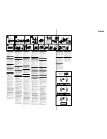
Exemple de montage (
6
)
Installation dans le tableau de bord
6
-
*
Remarque
Pendant l’installation de l’appareil, vérifiez que le
panneau avant de cet appareil est fermé.
Si le panneau avant est ouvert pendant l’installation et s’il
subit une force trop importante, un dysfonctionnement
risque de se produire.
Avertissement en cas d installation
dans une voiture dont le contact ne
comporte pas de position ACC
(accessoires)
Appuyez sur la touche
(OFF)
de l’appareil pendant
deux secondes pour désactiver l’affichage de
l’horloge après avoir coupé le moteur.
Si vous n’appuyez que brièvement sur
(OFF)
, l’affichage
de l’horloge ne disparaît pas, ce qui provoque la décharge
de la batterie.
Touche de r initialisation (
7
)
Quand l’installation et les raccordements sont terminés,
appuyez sur la touche de rèinitialisation avec un stylo à
bille, etc.
Installation du satellite de
commande (RM-X5S) (
8
)
Remarques
• Choisissez soigneusement l’endroit de montage afin que le
satellite de commande n’interfère pas avec les commandes
de la voiture.
• N’installez pas le satellite de commande dans un endroit
qui risque de compromettre la sécurité du passager avant
de quelque façon que ce soit.
• Lors de l’installation du satellite de commande, veillez à
ne pas endommager les câbles électriques, etc., situés de
l’autre côté de la surface de montage.
• Evitez d’installer le satellite de commande là où il risque
d’être soumis à des températures élevées comme sous le
rayonnement direct du soleil ou à côté d’une conduite de
chauffage, etc.
• Le commutateur de sélection Rev/Nor est situé dans la
partie inférieure du satellite de commande.
Sélectionnez “Nor” pour utiliser le satellite de commande
dans la position définie par défaut.
Sélectionnez “Rev” si vous montez le satellite de
commande du côté droit de la colonne de direction.
Conseil
Il est impossible de sélectionner Rev/Nor sur le côté de
l’appareil principal.
1 Appuyez sur les boutons et tournez les commandes
pour vérifier que l'appareil principal réagit
correctement.
Vous pouvez changer le sens des rayons IR en tournant
la molette située sur le satellite de commande.
Précaution
Assurez-vous que l’endroit où vous installez le satellite de
commande est à portée du récepteur de l’appareil.
2 Choisissez la position de montage exacte du
satellite de commande et nettoyez la surface de
montage.
Les souillures et l’huile altèrent le pouvoir adhérent de
l’adhésif double face.
3 Marquez la position pour la vis fournie.
Utilisez l’orifice de vissage du support de montage
0
pour marquer les positions.
Si vous ne parvenez pas à ajuster aisément le support de
montage
0
, découpez-le afin qu'il s'adapte à la colonne
de direction.
4 Déposez la garniture de la colonne de direction et
percez un trou de 2 mm de diamètre aux endroits
que vous avez marqués.
5 Chauffez la surface de montage et l’adhésif double
face sur le support de montage
0
à une
température comprise entre 20 °C et 30 °C et fixez
le support de montage sur la surface de montage
0
en exerçant une pression uniforme. Vissez
ensuite la vis
9
fournie.
Collez de la bande adhésive résistante, etc., de l’autre
côté de la surface de montage de manière à couvrir
l’extrémité saillante des vis de telle sorte qu’elle ne
puissent entrer en contact direct avec les câbles
électriques, etc., à l’intérieur de la colonne de direction.
6 Après avoir remonté le couvercle de la colonne de
direction, fixez le satellite de commande sur le
support de montage en alignant les quatre orifices
pratiqués à la base du satellite sur les quatre ergots
du support de montage et faites coulisser le
satellite de commande jusqu’à ce qu’il s’encliquette
dans sa position définitive comme illustré.
Précautions
• Lors de l’installation du satellite de commande près du
volant, veillez à bien fixer la courroie
qa
fournie.
• Assurez-vous que la courroie
qa
ne soit pas prise dans les
commandes du véhicule (levier de vitesses, etc.).
• Assurez-vous de bien serrer la vis de sécurité de la courroie
qa
après avoir accroché celle-ci au levier de changement
de direction, etc.
Conseil
Il existe deux orifices réservés à la courroie
qa
. Vous pouvez
utiliser indifféremment l’un ou l’autre.
Remarque
Si vous montez le satellite de commande sur la colonne de
direction, assurez-vous que l’extrémité saillante des vis à
l’intérieur de la colonne de direction n’entrave en aucune
façon le mouvement de l’axe, des organes de commande, des
commutateurs ou des câbles électriques, etc., à l’intérieur de
la colonne de direction.
Precautions
• Choose the installation location carefully so that the unit
will not interfere with normal driving operations.
• Avoid installing the unit in areas subject to dust, dirt,
excessive vibration, or high temperature, such as in direct
sunlight or near heater ducts.
• Use only the supplied mounting hardware for a safe and
secure installation.
Mounting angle adjustment
(CDX-M770/M670)
Adjust the mounting angle to less than 60°.
(MDX-M690)
Adjust the mounting angle to less than 20°.
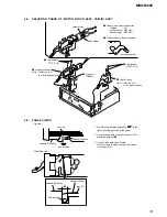
Extended portion of the front
panel (
4
)
How to detach and attach the
main display window (
5
)
Before installing the unit, detach the front panel.
5
-A To detach
1 Press
(OPEN)
on the unit for 2 seconds.
CD/MD playback or radio reception stops, and the front
panel automatically tilts at an angle of 30°.
2 Detach the main display window as illustrated.
After the main display window detaching is complete,
the front panel closes automaticaly.
5
-B To attach
Place the main display window on the front side of the unit
as illustrated, then lightly push the front panel into
position until it clicks.
Mounting example (
6
)
Installation in the dashboard
6
-
*
Note
When installing this unit, be sure to close the front
panel of the unit.
If the front panel is opened while installing and given too
much force, it may cause a malfunction.
Warning when installing in a car
without ACC (accessory) position
on the ignition key switch
Be sure to press
(OFF)
on the unit for two seconds to
turn off the clock display after turning off the engine.
When you press
(OFF)
only momentarily, the clock
display does not turn off and this causes battery wear.
Reset button (
7
)
When the installation and connections are completed, be
sure to press the Reset button with a ballpoint pen, etc.
Installing the rotary commander
(RM-X5S) (
8
)
Notes
• Choose the mounting location carefully so that the rotary
commander will not interfere with operating the car.
• Do not install the rotary commander where it may
jeopardize the safety of the (front) passenger in anyway.
• When installing the rotary commander, be sure not to
damage the electrical cables etc. on the other side of the
mounting surface.
• Avoid installing the rotary commander where it may be
subject to high temperatures, such as from direct sunlight
or hot air from the heater etc.
• The Rev/Nor-select switch is located on the bottom of the
rotary commander. Select “Nor” to use the rotary
commander as the factory-set position. Select “Rev” when
you mount the rotary commander on the right side of the
steering column.
Tip
Rev/Nor cannot be selected on the side of master unit.
1 Press the buttons and rotate the controls to make
sure that your master unit reacts well.
You can change the direction of infrared rays by turning
the dial on the rotary commander.
Caution
Be sure that the place where you install the rotary
commander is within the range of receptor on the unit.
2 Choose the exact location for the rotary
commander to be mounted, then clean the
mounting surface.
Dirt or oil impair the adhesive strength of the double-
sided adhesive tape.
3 Mark position for the supplied screw.
Use the screw holes on the mounting hardware
0
to
mark the positions.
If you cannot make the mounting hardware
0
fit easy,
cut the mounting hardware
0
to fit the steering wheel
column cover.
4 Remove the steering wheel column cover, and drill
2 mm diameter hole where you have marked.
5 Warm the mounting surface and the double-sided
adhesive tape on the mounting hardware
0
to the
temperature of 20 °C to 30 °C, and attach the
mounting hardware
0
onto the mounting surface
by applying even pressure. Then screw it down
with the supplied screw
9
.
Attach a piece of heavy duty tape etc. on the other side
of the mounting surface to cover the protruding tips of
the screws so that they will not interfere with the
electrical cables etc. inside the steering wheel column.
6 After installing the steering wheel column cover,
attach the rotary commander to the mounting
hardware by aligning the four holes on the bottom
of the rotary commander to the four catches on the
mounting hardware and sliding the rotary
commander until it locks into place as illustrated.
Cautions
• Be sure to attach the supplied strap
qa
when installing the
rotary commander near the steering wheel.
• Be sure that the strap
qa
does not get caught on the car
controls (gear, shifter, etc.).
• Be sure to tighten the stopper of the strap
qa
after
hanging the strap
qa
on the indicator switch, etc.
Tip
There are two holes for the strap
qa
. You can use whichever
hole you prefer.
Note
If you are mounting the rotary commander to the steering
wheel column, make sure that the protruding tips of the
screws on the inner surface of the column do not in anyway
hinder or interfere with the movement of the rotating shaft,
operative parts of the switches or the electrical cables etc.
inside the column.
Vorsichtsma§nahmen
• Wählen Sie den Einbauort sorgfältig so aus, daß das
Gerät beim Fahren nicht hinderlich ist.
• Bauen Sie das Gerät so ein, daß es keinen hohen
Temperaturen (keinem direkten Sonnenlicht, keiner
Warmluft von der Heizung), keinem Staub, keinem
Schmutz und keinen starken Vibrationen ausgesetzt ist.
• Für eine sichere Befestigung verwenden Sie stets nur die
mitgelieferten Montageteile.
Hinweis zum Montagewinkel
(CDX-M770/M670)
Das Gerät sollte in einem Winkel von weniger als 60°
montiert werden.
(MDX-M690)
Das Gerät sollte in einem Winkel von weniger als 20°
montiert werden.
berstehender Teil der
Frontplatte (
4
)
Abnehmen und Anbringen des
Haupt-Displays (
5
)
Nehmen Sie die Frontplatte vor dem Einbau des
Geräts ab.
5
-A Abnehmen
1 Drücken Sie 2 Sekunden lang
(OPEN)
am Gerät.
Die CD/MD-Wiedergabe bzw. der Radioempfang
stoppt, und die Frontplatte wird automatisch in einem
Winkel von 30 Grad geneigt.
2 Nehmen Sie das Haupt-Display wie in der
Abbildung dargestellt ab.
Wenn das Haupt-Display abgenommen ist, schließt sich
die Frontplatte automatisch.
5
-B Anbringen
Setzen Sie das Haupt-Display wie in der Abbildung
dargestellt an die Vorderseite des Geräts an, und drücken
Sie die Frontplatte dann leicht in die richtige Position, bis
sie mit einem Klicken einrastet.
Montagebeispiel (
6
)
Installation im Armaturenbrett
6
-
*
Hinweis
Achten Sie beim Einbau des Geräts darauf, die
Frontplatte geschlossen zu halten.
Wenn sich die Frontplatte beim Einbau öffnet und Sie zu
stark darauf drücken, kann es zu einer Fehlfunktion kommen.
Warnhinweis zur Installation des
Ger ts in einem Auto mit Z ndschlo§
ohne Zubeh rposition ACC oder I
Drücken Sie am Gerät unbedingt zwei Sekunden lang
(OFF)
, um die Uhrzeitanzeige auszuschalten,
nachdem Sie den Motor ausgeschaltet haben.
Wenn Sie
(OFF)
nur kurz drücken, wird die
Uhrzeitanzeige nicht ausgeschaltet, und der Autobatterie
wird Strom entzogen.
R cksetztaste (
7
)
Nach der Installation und dem Anschluß muß die
rücksetztaste mit einem Kugelschreiber o. ä. gedrückt werden.
Installieren des Joystick
(RM-X5S) (
8
)
Hinweise
• Wählen Sie den Montageort sorgfältig aus, so daß der
Joystick beim Fahren nicht im Wege ist.
• Montieren Sie den Joystick nicht an einer Stelle, an der er
eine Gefahr für den Beifahrer auf dem Vordersitz
darstellen könnte.
• Achten Sie bei der Montage des Joystick darauf, die
Elektrokabel an der anderen Seite der Montagefläche
nicht zu beschädigen.
• Montieren Sie den Joystick nicht an einer Stelle, an der er
hohen Temperaturen, zum Beispiel direktem Sonnenlicht
oder der Warmluft aus der Wagenheizung, ausgesetzt ist.
• Der Wählschalter Rev/Nor befindet sich an der Unterseite
des Joysticks. Wählen Sie „Nor“, wenn die werkseitig
voreingestellte Drehrichtung der Regler beibehalten
werden soll. Wählen Sie „Rev“, wenn Sie den Joystick auf
der rechten Seite der Lenksäule anbringen.
Tip
Rev/Nor kann nicht mit dem Hauptgerät ausgewählt werden.
1 Drücken Sie die Tasten, drehen Sie die Regler, und
vergewissern Sie sich, daß das Hauptgerät
entsprechend reagiert.
Sie können die Richtung der Infrarotstrahlen ändern,
indem Sie den Regler am Joystick drehen.
Vorsicht
Vergewissern Sie sich, daß der Montageort des Joysticks
innerhalb der Reichweite des Empfängers am Gerät ist.
2 Wählen Sie die Stelle aus, an der Sie den Joystick
montieren wollen, und reinigen Sie dann die
Montagefläche.
Staub oder Fettspuren beeinträchtigen die Haftung des
doppelseitigen Klebebandes.
3 Markieren Sie die Stelle zum Anbringen der
mitgelieferten Schraube.
Verwenden Sie dazu die Bohrung im Montageteil
0
.
Wenn das Montageteil
0
nicht auf die Abdeckung der
Lenkradsäule paßt, schneiden Sie es bitte zurecht.
4 Nehmen Sie die Abdeckung der Lenkradsäule ab,
und bohren Sie an der Stelle, die Sie gerade
markiert haben, ein Loch von 2 mm Durchmesser.
5 Erwärmen Sie die Montagestelle und das
doppelseitige Klebeband am Montageteil
0
auf
eine Temperatur von 20 bis 30 °C, und drücken Sie
dann das Montageteil
0
mit gleichmäßigem Druck
auf die Montagestelle. Befestigen Sie es dann mit
der mitgelieferten Schraube
9
.
Bringen Sie ein Stück sehr festes Klebeband o. ä. an der
Gegenseite der Montagefläche an, um die vorstehenden
Spitzen der Schrauben abzudecken, damit diese nicht
die Elektrokabel in der Lenkradsäule beschädigen
können.
6 Bringen Sie nun die Abdeckung der Lenkradsäule
wieder an, und befestigen Sie dann den Joystick
auf dem Montageteil, indem Sie die vier
Aussparungen an der Unterseite des Joysticks an
den vier Haken auf dem Montageteil ausrichten
und den Joystick daraufschieben, bis er einrastet,
wie auf der Abbildung zu sehen.
Vorsicht
• Achten Sie darauf, den mitgelieferten Riemen
qa
anzubringen, wenn Sie den Joystick in der Nähe des
Lenkrades installieren.
• Achten Sie darauf, daß sich der Riemen
qa
nicht an
Bedienelementen des Fahrzeugs verfängt (Schalthebel,
Handbremse usw.).
• Achten Sie darauf, den Stopper des Riemens
qa
anzuziehen, nachdem Sie den Riemen
qa
an den
Blinkerhebel o. ä. gehängt haben.
Tip
Für den Riemen
qa
sind zwei Aussparungen vorhanden. Sie
können sie nach Belieben auswählen.
Hinweis
Wenn Sie den Joystick an der Lenkradsäule montieren,
achten Sie darauf, daß die vorstehenden Spitzen der
Schrauben an der Innenfläche der Lenkradsäule die
Bewegung der Lenkwelle, die Funktionsteile der Schalter
bzw. die Elektrokabel innerhalb der Lenkradsäule in keiner
Weise behindern.
Voorzorgsmaatregelen
• Kies de installatieplaats zorgvuldig zodat het toestel de
bestuurder niet hindert tijdens het rijden.
• Installeer het apparaat niet op plaatsen waar het
blootgesteld wordt aan hoge temperaturen, b.v. in direct
zonlicht of bij de warme luchtstroom van de
autoverwarming, aan sterke trillingen, of waar het in
contact komt met veel stof of vuil.
• Gebruik voor het veilig en stevig monteren van het
apparaat uitsluitend de bijgeleverde montage-
onderdelen.
Maximale montagehoek
(CDX-M770/M670)
Installeer het apparaat nooit onder een hoek van meer
dan 60° met het horizontale vlak.
(MDX-M690)
Installeer het apparaat nooit onder een hoek van meer
dan 20° met het horizontale vlak.
Verlengstuk van het frontpaneel
(
4
)
Het hoofddisplay losmaken en
bevestigen (
5
)
Verwijder, alvorens met het installeren te beginnen,
het afneembare voorpaneel.
5
-A Verwijderen
1 Hou
(OPEN)
op het toestel 2 seconden ingedrukt.
CD/MD-weergave of radio-ontvangst stopt en het
frontpaneel kantelt automatisch in een hoek van 30
graden.
2 Maak het hoofddisplay los zoals de afbeelding laat
zien.
Nadat het hoofddisplay volledig is losgemaakt, sluit het
frontpaneel automatisch.
5
-B Bevestigen
Plaats het hoofddisplay vooraan op het toestel zoals de
afbeelding laat zien en druk het vervolgens lichtjes op zijn
plaats tot het vastklikt.
Montagevoorbeeld (
6
)
Montage in het dashboard
6
-
*
Opmerking
Bij het installeren van het toestel dient het
frontpaneel te zijn gesloten.
Als het frontpaneel tijdens het installeren open is, kan het
worden geforceerd wat tot een defect kan leiden.
Opgelet bij het monteren in een auto
waarvan het contactslot geen ACC
(accessory) stand heeft
Druk
(OFF)
op het toestel gedurende twee seconden
in om de klokweergave uit te schakelen na het
afzetten van de motor.
Indien u slechts even op
(OFF)
drukt, verdwijnt de
tijdindicatie niet waardoor de batterij uitgeput raakt.
Terustelknop (
7
)
Druk, nadat u het apparaat heeft geïnstalleerd en de
aansluitingen heeft gemaakt, met een balpen of een ander
puntig voorwerp op de terustelknop.
Installatie van de
bedieningssatelliet (RM-X5S) (
8
)
Opmerkingen
• Ga zorgvuldig te werk bij het kiezen van een geschikte
montagepositie zodat de bedieningssatelliet u nooit
hindert bij het rijden.
• Installeer de bedieningssatelliet nooit op een plaats waar
hij de veiligheid van de (voor)passagier in gevaar kan
brengen.
• Bij het installeren van de bedieningssatelliet moet u erop
letten dat u de elektrische bedrading en dergelijke aan de
andere kant van het montagevlak niet beschadigt.
• Installeer de bedieningssatelliet niet op plaatsen waar hij
blootstaat aan hoge temperaturen, bijvoorbeeld door
rechtstreekse zonnestraling of warme lucht afkomstig van
de verwarming, enz.
• De Rev/Nor-keuzeschakelaar bevindt zich onderaan op de
bedieningssatelliet.
Kies “Nor” om de bedieningssatelliet te gebruiken met de
fabrieksinstelling.
Kies “Rev” wanneer u de bedieningssatelliet rechts op de
stuurkolom monteert.
Tip
Rev/Nor kan niet worden geselecteerd op het
hoofdtoestel.
1 Druk op de toetsen en draai aan de regelaars om
zeker te zijn dat uw master unit goed functioneert.
U kunt de richting van de infraroodstralen wijzigen
door aan de knop op de bedieningssatelliet te draaien.
Let op!
Zorg ervoor dat u de bedieningssatelliet installeert
binnen het ontvangstbereik van het toestel.
2 Kies de exacte installatieplaats voor de
bedieningssatelliet en maak vervolgens het
montagevlak schoon.
Vuil of vet tasten het kleefvermogen van het
dubbelzijdige plakband aan.
3 Markeer een bevestigingspunt voor de
meegeleverde schroef.
Markeer de posities aan de hand van de schroefgaten
in het bevestigingselement
0
.
Als het bevestigingselement
0
niet goed past, moet u
het overtollige gedeelte afsnijden zodat het wel in de
stuurkolombekleding past.
4 Verwijder de stuurkolombekleding en boor een gat
van 2 mm op de gemarkeerde posities.
5 Warm het bevestigingsvlak en de dubbelzijdige
kleefband op het bevestigingselement
0
op tot
een temperatuur van 20 à 30 °C en plaats de steun
op het bevestigingsvlak door gelijkmatig aan te
drukken. Schroef hem vervolgens vast met de
meegeleverde schroef
9
.
Breng een stuk tape of iets dergelijks aan op de andere
kant van het bevestigingsvlak om te voorkomen dat de
uitstekende schroefpunten in contact komen met de
elektrische bedrading en dergelijke binnenin de
stuurkolom.
6 Plaats de stuurkolombekleding terug en bevestig
de bedieningssatelliet op het montage-accessoire
door de vier gaten onderaan de bedieningssatelliet
te laten samenvallen met de vier
bevestigingsklemmen op het montage-accessoire
en verschuif de bedieningssatelliet tot hij op zijn
plaats klikt zoals de illustratie laat zien.
Let op!
• Bevestig de meegeleverde riem
qa
wanneer u de
bedieningssatelliet in de buurt van het stuurwiel
monteert.
• Zorg ervoor dat riem
qa
niet kan verstrikt raken in de
bedieningselementen van de auto (schakelpook enz).
• Zet de stopper op de riem
qa
vast nadat u deze hebt
bevestigd aan de richtingaanwijzerhendel enz
Tip
Er zijn twee gaten voor riem
qa
. U kunt kiezen welk ervan
u gebruikt.
Opmerking
Bij het monteren van de bedieningssatelliet op de
stuurkolom, moet u ervoor zorgen dat de uitstekende
punten van de schroeven aan de binnenkant van de
stuurkolom de stuurstang, schakelaars, elektrische
bedrading, enzovoort in de stuurkolom niet hinderen.
Precauzioni
• Scegliere con attenzione la posizione per l’installazione in
modo che l’apparecchio non interferisca con le operazioni
di guida del conducente.
• Evitare di installare l’apparecchio dove sia soggetto ad
alte temperature, come alla luce solare diretta o al getto di
aria calda dell’impianto di riscaldamento, o dove possa
essere soggetto a polvere, sporco e vibrazioni eccessive.
• Usare solo il materiale di montaggio in dotazione per
un’installazione stabile e sicura.
Regolazione dell angolo di montaggio
(CDX-M770/M670)
Regolare l’angolo di montaggio in modo che sia inferiore a 60°.
(MDX-M690)
Regolare l’angolo di montaggio in modo che sia inferiore a 20°.
parte sporgente del pannello
anteriore (
4
)
Come rimuovere e applicare la
finestra del display principale (
5
)
Prima di installare l’apparecchio rimuovere il pannello
anteriore.
5
-A Per rimuoverlo
1 Premere
(OPEN)
sull’apparecchio per 2 secondi.
la riproduzione di CD/MD o la ricezione radio si
arresta, quindi il pannello anteriore si inclina
automaticamente di 30 gradi.
2 Rimuovere la finestra del display principale, come
illustrato.
Una volta completata la rimozione della finestra del
display principale, il pannello anteriore si chiude
automaticamente.
5
-B Per reinserirlo
Posizionare la finestra del display principale sul lato
anteriore dell’apparecchio come illustrato, quindi spingere
il pannello anteriore evitando di esercitare eccessiva
pressione fino a quando non scatta in posizione.
Esempio di montaggio (
6
)
Installazione nel cruscotto
6
-
*
Nota
Durante l’installazione dell’apparecchio, assicurarsi
di chiudere il relativo pannello anteriore.
Se durante l’installazione il pannello anteriore è aperto e
viene esercitata eccessiva forza, è possibile che si
verifichino problemi di funzionamento.
Informazioni importanti per quando
si effettua l installazione su un auto
sprovvista della posizione ACC
sull interruttore di accensione
Assicurarsi di premere
(OFF)
sull’apparecchio per due
secondi per spegnere il display dell’orologio dopo che
il motore è stato spento.
Se si preme
(OFF)
solo per un attimo, il display
dell’orologio non si spegne causando in questo modo lo
scaricamento della batteria.
Tasto di azzeramento (
7
)
Dopo avere terminato l’installazione e i collegamenti,
assicurarsi di premere il tasto di azzeramento con la punta
di una penna a sfera, ecc.
Installazione del telecomando a
rotazione (RM-X5S) (
8
)
Note
• Scegliere attentamente la posizione di montaggio in modo
che il telecomando a rotazione non interferisca con la guida.
• Non installare il telecomando a rotazione in posizione tale
da poter compromettere in alcun modo la sicurezza del
passeggero.
• Al momento di installare il telecomando a rotazione
assicurarsi di non danneggiare i cavi elettrici ecc. nella parte
posteriore della superficie di montaggio.
• Non installare il telecomando a rotazione in posizione
soggetta ad alte temperature, ad esempio esposto alla luce
solare diretta o al calore proveniente dall’impianto di
riscaldamento della vettura.
• L’interruttore di selezione Rev/Nor è situato nella parte
inferiore del telecomando a rotazione.
Selezionare “Nor” per utilizzare il telecomando a rotazione
con le impostazioni di fabbrica. Selezionare “Rev” quando il
telecomando a rotazione viene montato sul lato destro del
piantone di guida.
Suggerimento
Non è possibile selezionare Rev/Nor dall’unità principale.
1 Premere i tasti e ruotare i comandi per verificare che
l'apparecchio principale funzioni correttamente.
È possibile cambiare la direzione dei raggi infrarossi
ruotando la manopola sul telecomando a rotazione.
Attenzion
Assicurarsi che il luogo in cui viene installato il telecomando
a rotazione sia all’interno della gamma del ricettore
dell’unità principale.
2 Scegliere la posizione esatta di montaggio del
telecomando a rotazione, quindi pulire la superficie
di montaggio.
La sporcizia o l’unto possono pregiudicare la tenuta del
nastro biadesivo.
3 Segnare la posizione di montaggio per la vite in
dotazione.
Usare il foro per la vite sulla staffa di montaggio
0
per
segnare la posizione.
Se non è possibile installare la staffa di montaggio
0
facilmente; tagliare la staffa di montaggio
0
per
adattarla alla copertura del piantone di guida.
4 Rimuovere il coperchio della colonna del volante e
praticare un foro di 2 mm di diametro nella
posizione contrassegnata.
5 Riscaldare la superficie di montaggio e il nastro
biadesivo sulla staffa di montaggio
0
ad una
temperatura compresa tra 20 °C e 30 °C. Applicare
la staffa di montaggio
0
sulla superficie di
montaggio esercitando una pressione omogenea,
quindi fissarla avvitando la vite
9
in dotazione.
Applicare una striscia di nastro adesivo pesante sull’altro
lato della superficie di montaggio in modo da coprire la
punta sporgente delle viti perché queste non interferiscano
con i cavi elettrici all’interno della colonna del volante.
6 Dopo aver rimontato il coperchio della colonna del
volante, montare il telecomando allineando i
quattro fori sul fondo del comando ai quattro fermi
sulla staffa di montaggio e facendo scorrere il
telecomando fino a che non si blocca in posizione,
come illustrato in figura.
Attenzione
• Assicurarsi di inserire il cordino
qa
in dotazione quando si
installa il telecomando a rotazione vicino al volante.
• Assicurarsi che il cordino
qa
non rimanga incastrato tra i
comandi dell’automobile (cambio, pedali, ecc.).
• Assicurarsi di stringere il fermo del cordino
qa
dopo aver
applicato il cordino
qa
all’interruttore dell’indicatore e così
via.
Suggerimento
Esistono due fori per il cordino
qa
.
Utilizzare indifferentemente uno dei due.
Nota
Se il telecomando viene montato sulla colonna del volante,
assicurarsi che le punte sporgenti delle viti sulla superficie
interna della colonna non pregiudichino o interferiscano in
alcun modo con il movimento dell’albero, con i componenti
degli interruttori o con i cavi elettrici etc. all’interno della
colonna.
1
Dashboard
Armaturenbrett
Tableau de bord
Cruscotto
Dashboard
Fire wall
Motorraumtrennwand
Paroi ignifuge
Parete tagliafiamma
Brandschot
Bend these claws outward for a tight fit, if
necessary.
Falls erforderlich, diese Klammern für einen
sicheren Halt hochbiegen.
Pliez ces griffes pour assurer une prise
correcte si nécessaire.
Piegare questi morsetti per un‘installazione
più sicura, se necessario.
Indien nodig kunt u deze lipjes ombuigen
voor een steviger bevestiging.
7
7
5
7
5
5
4
2
3
1
1
5
6
A
B
2
3
4
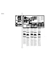
Power connection diagram
Auxiliary power connector may vary depending on the
car. Check your car’s auxiliary power connector diagram
to make sure the connections match correctly. There are
three basic types (illustrated below). You may need to
switch the positions of the red and yellow leads in the car
stereo’s power connecting cord.
After matching the connections and switched power
supply leads correctly, connect the unit to the car’s power
supply. If you have any questions and problems
connecting your unit that are not covered in this manual,
please consult the car dealer.
Stromanschlu§diagramm
Der Hilfsstromanschluß kann je nach Fahrzeugtyp
unterschiedlich sein. Sehen Sie im
Hilfsstromanschlußdiagramm für Ihr Fahrzeug nach, wie
die Verbindung ordnungsgemäß vorgenommen werden
muß. Es gibt, wie unten abgebildet, drei grundlegende
Typen. Sie müssen möglicherweise die rote und gelbe
Leitung des Stromversorgungskabels der
Autostereoanlage vertauschen.
Stellen Sie die Anschlüsse her, schließen Sie die
geschalteten Stromversorgungsleitungen richtig an, und
verbinden Sie dann das Gerät mit der Stromversorgung
Ihres Fahrzeugs. Wenn beim Anschließen des Geräts
Fragen oder Probleme auftreten, die in dieser
Bedienungsanleitung nicht erläutert werden, wenden Sie
sich bitte an den Autohändler.
Sch ma de connexion
d alimentation
Le connecteur d’alimentation auxiliaire peut varier
suivant le type de voiture. Vérifiez le schéma du
connecteur d’alimentation auxiliaire de votre voiture
pour vous assurer que les connexions correspondent. Il
en existe trois types de base (illustrés ci-dessous). Il se
peut que vous deviez commuter la position du fil rouge
et jaune du cordon d’alimentation de l’autoradio.
Après avoir établi les connexions et commuté
correctement les fils d’alimentation, raccordez l’appareil à
l’alimentation de la voiture. Si vous avez des questions
ou des difficultés à propos de cet appareil qui ne sont pas
abordées dans le présent mode d’emploi, consultez votre
revendeur automobile.
Auxiliary power connector
Hilfsstromanschluß
Connecteur d’alimentation auxiliaire
Connettore di alimentazione ausiliare
Hulpvoedingsaansluiting
4
Yellow
Gelb
Jaune
Giallo
Geel
continuous power supply
permanente Stromversorgung
alimentation continue
alimentazione continua
continu voeding
the car without ACC position
Fahrzeug ohne Zubehörposition (ACC)
Voiture sans position ACC
la macchina senza posizione ACC
Wagen zonder ACC stand
Red
Rot
Rouge
Rosso
Rood
Red
Rot
Rouge
Rosso
Rood
Yellow
Gelb
Jaune
Giallo
Geel
Yellow
Gelb
Jaune
Giallo
Geel
Red
Rot
Rouge
Rosso
Rood
switched power supply
geschaltete Stromversorgung
alimentation commutée
alimentazione commutata
geschakelde voeding
7
4
Yellow
Gelb
Jaune
Giallo
Geel
switched power supply
geschaltete Stromversorgung
alimentation commutée
alimentazione commutata
geschakelde voeding
Red
Rot
Rouge
Rosso
Rood
Red
Rot
Rouge
Rosso
Rood
Yellow
Gelb
Jaune
Giallo
Geel
Yellow
Gelb
Jaune
Giallo
Geel
Red
Rot
Rouge
Rosso
Rood
continuous power supply
permanente Stromversorgung
alimentation continue
alimentazione continua
continu voeding
7
Red
Rot
Rouge
Rosso
Rood
Red
Rot
Rouge
Rosso
Rood
Yellow
Gelb
Jaune
Giallo
Geel
Yellow
Gelb
Jaune
Giallo
Geel
8
2
3
4
1
Infrared rays dial
Regler für Infrarotstrahlen
Molette de réglage des rayons IR
Manopola raggi infrarossi
Knop infraroodstralen
5
0
9
6
Heavy duty tape etc.
Sehr festes Klebeband o. ä.
Bande adhésive résistante, etc.
Nastro adesivo pesante.
Sterke kleefband of dergelijke
the other hole
die andere Aussparung
l’autre orifice
altro foro
ander gat
Holes
Aussparungen
Orifices
Fori
Gaten
qa
qa
Diagramma dei collegamenti di
alimentazione
Il connettore di alimentazione ausiliaria può variare a
seconda della macchina. Controllare il diagramma del
connettore di alimentazione ausiliaria della macchina per
essere sicuri che le connessioni corrispondano
correttamente. Vi sono tre tipi di base (illustrazione
sotto). Potrà essere necessario cambiare le posizioni dei
conduttori rosso e giallo nel cavo di alimentazione dello
stereo della macchina.
Dopo aver fatto corrispondere le connessioni e i cavi di
alimentazione commutata, collegare l’apparecchio
all’alimentazione della macchina. Se si hanno domande o
se sorgono problemi che non sono stati trattati nel
manuale nel collegare l’apparecchio, contattare
l’autoconcessionario.
Voedingsaansluitschema
De hulpvoedingsaansluiting kan verschillen naargelang
van de wagen. Controleer het voedingsaansluitschema
dat bij dit toestel wordt geleverd om te zien of de
aansluitingen kloppen. Er zijn drie basistypes (zie
illustratie hieronder).
Als de aansluitingen en geschakelde voedingskabels
kloppen, sluit u het toestel aan op de voeding van de
wagen. Indien u nog vragen of problemen hebt in
verband met het aansluiten van het toestel die niet in
deze handleiding vermeld staan, raadpleeg dan de
autodealer.
7
Mounting example
Montagebeispiel
Exemple de montage
Rev
Nor
Extended portion of the front panel
Überstehender Teil der Frontplatte
Partie étendue de la façade
Parte sporgente del pannello anteriore
Verlengstuk van het frontpaneel
7 mm
20 mm
4
(OPEN)
c
Esempio di montaggio
Montagevoorbeeld
*
Summary of Contents for MDX-M690
Page 79: ...79 MDX M690 MEMO ...

