background image

MFM-HT75W/HT95

US Model

Canadian Model

AEP Model

E Model

TFT LCD COLOR COMPUTER DISPLAY

SERVICE MANUAL

2

PROG

PROG

Summary of Contents for MFM-HT75W

Page 1: ...MFM HT75W HT95 US Model Canadian Model AEP Model E Model TFT LCD COLOR COMPUTER DISPLAY SERVICE MANUAL 2 PROG PROG ...

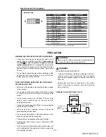
Page 2: ... 48kHz Vertical 48 85Hz Digital 60Hz MFM HT95 Horizontal 28 86kHz Digital 64kHz Vertical 48 85Hz Digital 60Hz 1280x1024 48 75Hz Digital 60Hz 1280x1024 4 Max Resolution Analog 1280 x 1024 75Hz DVI Analog Digital 1280 x 768 60Hz MFM HT75W 1280 x 1024 60Hz MFM HT95 5 POWER SUPPLY 5 1 Power AC 100 240V 50 60Hz 1 0A 5 2 Power Consumption 6 ENVIRONMENT 6 1 Operating Temperature 5 C 35 C 6 2 Relative Hum...

Page 3: ...IT Must mount the module using mounting holes arranged in four corners Do not press on the panel edge of the frame strongly or electric shock as this will result in damage to the screen Do not scratch or press on the panel with any sharp objects such as pencil or pen as this may result in damage to the panel Protect the module from the ESD as it may damage the electronic circuit C MOS Make certain...

Page 4: ...t the test receiver ground lead to the receiver chassis ground before connecting the test receiver positive lead Always remove the test receiver ground lead last 9 Use with this receiver only the test fixtures specified in this service manual CAUTION Do not connect the test fixture ground strap to any heat sink in this receiver Electrostatically Sensitive ES Devices Some semiconductor solid state ...

Page 5: ...ng iron tip as the solder melts 2 Draw away the melted solder with an anti static suction type solder removal device or with solder braid before removing the IC Replacement 1 Carefully insert the replacement IC in the circuit board 2 Carefully bend each IC lead against the circuit foil pad and solder it 3 Clean the soldered areas with a small wire bristle brush It is not necessary to reapply acryl...

Page 6: ...the IC connection 4 Route the jumper wire along the path of the out away copper pattern and let it overlap the previously scraped end of the good copper pattern Solder the overlapped area and clip off any excess jumper wire At Other Connections Use the following technique to repair the defective copper pattern at connections other than IC Pins This technique involves the installation of a jumper w...

Page 7: ...800 x 600 V Lines 72 188 666 600 37 6 23 12 H Pixels 49 5 46 875 1056 800 16 80 160 800 x 600 V Lines 75 000 625 600 1 3 21 13 H Pixels 56 250 53 674 1048 800 32 64 152 800 x 600 V Lines 85 061 631 600 1 3 27 14 H Pixels 56 750 53 741 1056 800 48 80 128 800 x 600 V Lines 84 898 633 600 3 4 26 15 H Pixels 57 285 49 727 1152 832 32 64 224 832 X 624 V Lines 74 553 667 624 3 3 37 16 H Pixels 65 0 48 3...

Page 8: ... 74 553 667 624 3 3 37 13 H Pixels 65 000 48 363 1344 1024 24 136 160 1024 x 768 V Lines 60 004 806 768 3 6 29 14 H Pixels 75 000 56 476 1328 1024 24 136 144 1024 x 768 V Lines 70 069 806 768 3 6 29 15 H Pixels 78 750 60 023 1312 1024 16 96 176 1024 x 768 V Lines 75 029 800 768 1 3 28 16 H Pixels 80 000 60 241 1328 1024 32 96 176 1024 x 768 V Lines 74 927 804 768 3 3 30 17 H Pixels 94 500 68 677 1...

Page 9: ... 27 000 31 250 864 720 12 64 68 720 x 576 V Lines 50 000 625 576 5 5 39 5 H Pixels 74 250 28 125 2640 1920 528 44 148 1920 x 1080 V Lines 25 00 1125 1080 2 5 38 6 H Pixels 74 250 33 750 2200 1920 44 44 192 1920 x 517 V Lines 60 053 562 517 5 5 35 7 H Pixels 74 250 33 750 2200 1920 44 44 192 1920 x 5400 V Lines 60 053 562 540 2 5 15 8 H Pixels 74 250 45 000 1650 1280 60 40 270 1280 x 720 V Lines 60...

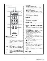
Page 10: ... change the TV channel 8 and volume control buttons Use to select the menu items and to make adjustments and also display the Volume adjustment bar to control the volume 9 input select OK button This button functions in two ways As the button this button switches the input signal between PC 1 PC 2 TV VIDEO 1 and VIDEO 2 when two computers and two pieces of video equipment are connected As the OK b...

Page 11: ...n connected to the audio output jack of a computer or other equipment connected to PC 2 18 VHF UHF jack This jack inputs a signal from an aerial 19 VIDEO 2 jacks 19 1 Composite S video input jacks for VIDEO 2 These jacks input composite video or S video signals When you connect video equipment to both composite video input and S video input jacks the signal from the S video jack is displayed 19 2 ...

Page 12: ...ayed will remain until you press this button again 10 muting button Press to turn the sound off Press again or press the button to restore the sound 11 and OK buttons Use the buttons to select menu items and make adjustments Press the OK button to activate the selected menu item and adjustments made using the buttons 12 jump button Press to switch the TV channel between the current one and the las...

Page 13: ...r at the Back cabinet then screw cover will be departed 4 Please lift the left side edge of under Back cabinet with fingertip like picture then latch will be departed 5 Please lift the right side of under Back cabinet with fingertip like picture then latch will be departed 6 Please pull the left side of Back cabinet like picture then latch will be departed 7 Please pull the upper side of Back cabi...

Page 14: ...htness in 9300k 6500k user color mode D AGING Select aging mode on off E CLEAR ETI Initilize the used time of MFT F CLEAR EEPROM Initilize the EDID DATA at DDC2B EEPROM is saved system memory Process Press ok button and then power key G DEFAULT TIMING1 Select the resolution timing of the signal Menu is 1152 x 864 VESA standard timing 1152x870 MAC computer timing H DEFAULT TIMING2 Select the resolu...

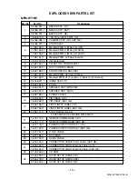
Page 15: ...MFM HT75W HT95 E 15 EXPLODED VIEW 20 1 2 7 5 18 8 6 11 3 17 14 13 4 12 19 9 10 15 16 ...

Page 16: ...or 13 X 2048 971 1 HINGE ASSY 17 14 2 582 782 01 DOOR 15 1 826 024 11 SPEAKER UNIT WOOFER 16 1 826 034 11 SPEAKER UNIT SIDE 17 2 582 783 01 SCREW COVER 18 1 830 333 11 PIN CABLE U C 1 830 385 11 PIN CABLE AEP GE 19 2 582 796 01 VIDEO INPUT LABEL U C 2 582 796 11 VIDEO INPUT LABEL AEP GE 20 4 095 701 11 SONY BADGE No 5 5 ACCESSORIES PACKING MATERIALS 21 1 479 112 11 REMOTE COMMANDER U C 1 479 111 1...

Page 17: ...sor 13 X 2048 987 1 HINGE ASSY 19 14 2 582 782 01 DOOR 15 1 826 024 11 SPEAKER UNIT WOOFER 16 1 826 034 11 SPEAKER UNIT TWEETER 17 2 582 783 01 SCREW COVER 18 1 830 333 11 PIN CABLE U C 1 830 385 11 PIN CABLE AEP GE 19 2 582 796 01 VIDEO INPUT LABEL U C 2 582 796 11 VIDEO INPUT LABEL AEP GE 20 4 095 701 11 SONY BADGE No 5 5 ACCESSORIES PACKING MATERIALS 21 1 479 112 11 REMOTE COMMANDER U C 1 479 1...

Page 18: ...9 878 331 01 English 2005DR02 1 Made in Japan 2005 4 MFM HT75W HT95 E Sony EMCS Corporation Ichinomiya Tec ...

Reviews: