84
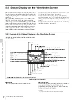
Status Display on the Viewfinder Screen
Chap
te
r 5
Men
u
Dis
p
la
ys
a
nd Det
a
iled
S
e
ttin
gs
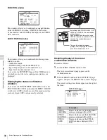
A:
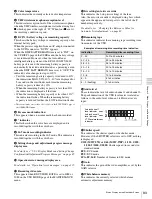
Displayed when the WHITE BAL switch is set to A.
B:
Displayed when the WHITE BAL switch is set to B.
P:
Displayed when the WHITE BAL switch is set to PRST
or when the preset button on the RM-B150/B750 has
been pushed.
T:
Displayed when ATW is being used.
r
Filter
This indicates the currently selected filter types.
s
D5600 indication
This appears when the electric 5600K color temperature
filter function has been activated on the FUNCTION 2
page of the MAINTENANCE menu.
t
Time code
This indicates the time code, user bits or other information
selected by the DISPLAY switch and DATA DISPLAY
switch settings.
For more information, see “Relationships between the
DISPLAY switch and DATA DISPLAY switch settings and
the time counter displays” on page 32.
u
ID number
This indicates the ID number selected from ID 1 to ID 4.
The ID number is recorded together with the color bars.
v
Date and time
This indicates the date and time of recording, which are
recorded together with the color bars.
w
Model name and serial number
This indicates the model name and serial number of the
camcorder, which are recorded together with the color
bars.
x
16:9 mode
This indicates the 16:9 mode.
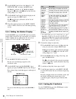
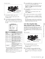
5-2-2 Selecting the Display Items
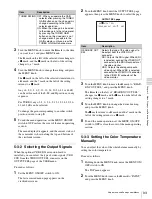
To select the items to be displayed on the viewfinder screen
from the VF DISP 1 and VF DISP 2 pages of the USER
menu, turn on or off the indication next to each item.
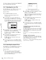
To select the items to be displayed on the viewfinder
screen, proceed as follows:
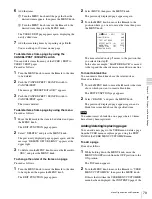
1
Set the MENU ON/OFF switch to ON.
The last accessed menu page appears on the
viewfinder screen.
2
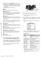
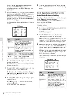
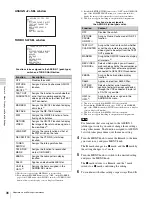
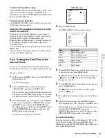
Turn the MENU knob until the VF DISP 1 or VF DISP
2 page appears, and press the MENU knob to select the
page.
The current setting is displayed on the right of each
item.
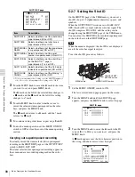
VF DISP 1 page
You can select the following items to be displayed on
the screen on the VF DISP 1 or VF DISP 2 page.
VF DISP 1 page
1) The viewfinder display can be also turned on or off by using the
DISPLAY switch on the viewfinder.
2) For detailed information on the display mode, see
Modes and Setting Change Confirmation/Adjustment Progress
Messages” on page 85
Item
Description
VF DISP
Turning on or off the viewfinder
display
1)
VF DISP MODE
Selecting the display mode
2)
DISP EXTENDER
Extender indicator
DISP FILTER
Types of the ND and CC filters
DISP WHITE
White balance memory indicator
DISP GAIN
Gain indicator
DISP SHUTTER
Shutter speed and ECS mode
indicator
DISP AUDIO
Audio level indicator
DISP TAPE
Remaining tape indicator
DISP IRIS
Iris opening indicator
CANCEL/PRST /
ESCAPE switch
MENU ON/OFF switch
MENU knob
U04 VF DISP 1
VF DISP : ON
VF DISP MODE : 3
DISP EXTENDER : ON
DISP FILTER : ON
DISP WHITE : ON
DISP GAIN : ON
DISP SHUTTER : ON
DISP AUDIO : ON
DISP TAPE : ON
DISP IRIS : ON
Summary of Contents for MSV-970
Page 5: ...5 ...
Page 168: ...168 Index Index ...
Page 170: ...Sony Corporation MSW 970 970P SY 3 863 920 03 1 Printed in Japan 2006 11 13 2005 ...


