86
Status Display on the Viewfinder Screen
Chap
te
r 5
Men
u
Dis
p
la
ys
a
nd Det
a
iled
S
e
ttin
gs
2
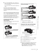
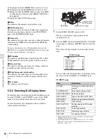
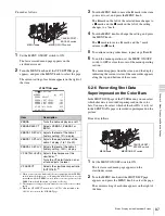
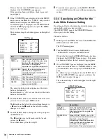
Turn the MENU knob to move the
b
mark to “VF
DISPLAY MODE,” and press the MENU knob.
The
b
mark on the left of “VF DISPLAY MODE”
changes to a
z
mark, and the
z
mark on the left of the
setting changes to a ? mark.
3
Turn the MENU knob until the desired display mode
appears, and press the MENU knob.
The
z
mark returns to a
b
mark, and the ? mark
returns to a
z
mark.
4
To end the menu operation, set the MENU ON/OFF
switch to OFF or close the cover of the menu operating
section.
5-2-4 Setting the Marker Display
Use the MARKER 1 page of the USER menu to switch the
display of the center and safety zone markers on or off and
to select whether the area indicated by the safety zone
marker is 80%, 90% or 100% of the screen area.
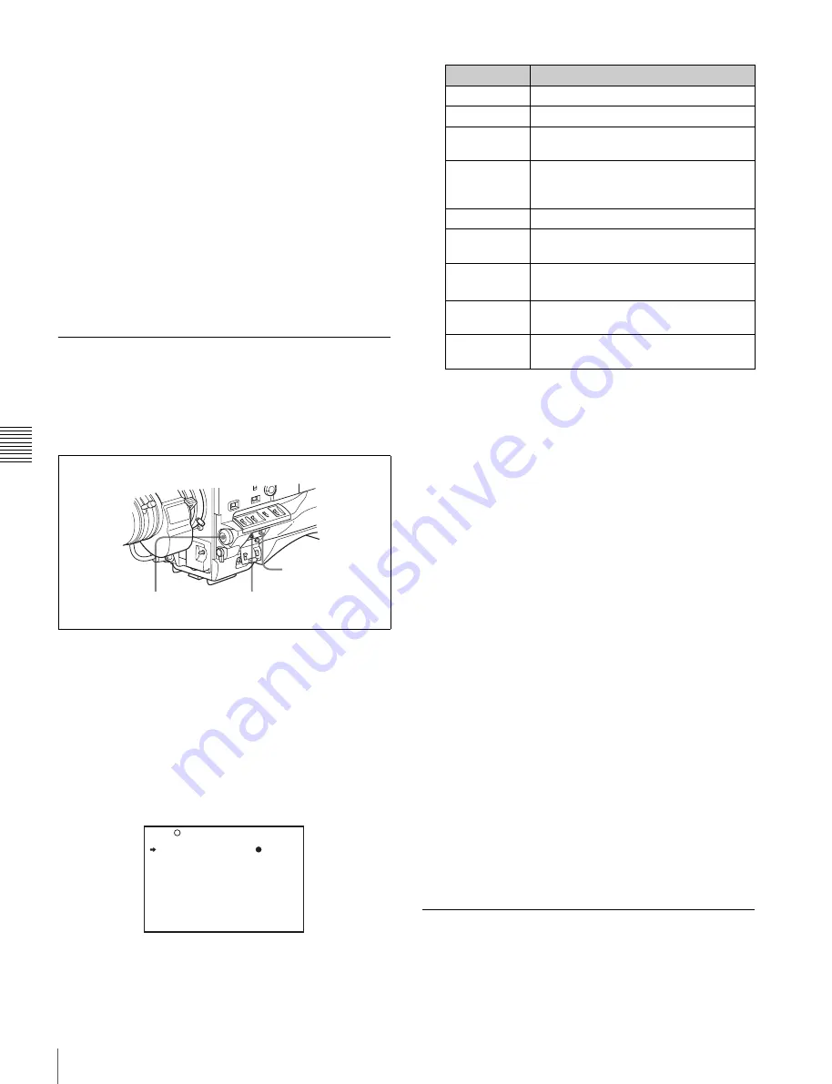
1
Set the MENU ON/OFF switch to ON.
The last accessed menu page appears on the
viewfinder screen.
2
Turn the MENU knob until the MARKER 1 page
appears, and press the MENU knob to select the page.
The current setting of each item appears on the right of
the item.
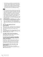
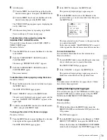
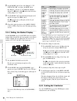
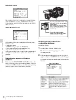
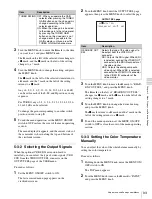
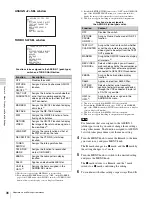
MARKER 1 page
You can set the following items on the MARKER 1
page.
1) The ASPECT MASK item is for processing the signal to be output to
the viewfinder. When R, G, or B is selected for the TEST OUT
SELECT item from the menu, the same video signal is output to the
viewfinder and the TEST OUT connector. Thus, when the ASPECT
MASK item is set to “ON” with R/G/B selected, the masked video
signal is output to the TEST OUT connector.
3
Perform the settings for each item.
1
Turn the MENU knob to move the
b
mark to the
item you want to set, and press MENU knob.
The
b
mark on the left of the selected item changes
to the
z
mark, and the
z
mark on the left of the
setting changes to a ? mark.
2
Turn the MENU knob to change the setting, and
press the MENU knob.
The
z
mark on the left of the selected item returns
to a
b
mark, and the ? mark on the left of the setting
returns to a
z
mark.
4
To continue setting other items, repeat step
3
.
5
To end the menu operation, set the MENU ON/OFF
switch to OFF or close the cover of the menu operating
section.
The menu disappears from the viewfinder screen, and
the display indicating the current status of the
camcorder appears along the top and bottom of the
screen.
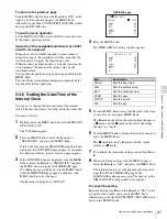
5-2-5 Setting the Viewfinder
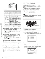
Use the VF SETTING page of the USER menu to select
items related to the viewfinder.
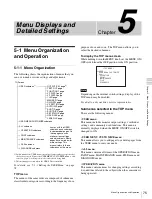
CANCEL/PRST /
ESCAPE switch
MENU knob
MENU ON/OFF switch
U07 MARKER 1
MARKER :
OFF
CENTER : OFF
SAFETY ZONE : OFF
SAFETY AREA : 90%
ASPECT : OFF
ASPECT SELECT : 4:3
ASPECT MASK : OFF
ASPECT MASK LVL : 1/4
100% MARKER : OFF
TOP
Item
Description
MARKER
Not to display all markers, set to OFF.
CENTER
To display the center marker, set to ON.
SAFETY
ZONE
To display the safety zone, set to ON.
SAFETY
AREA
To select the safety zone range (80%,
90%, 92.5% or 95%), when SAFETY
ZONE is set to ON.
ASPECT
To display the aspect marker, set to ON.
ASPECT
SELECT
To select the type (4:3, 13:9, 14:9) of
the aspect marker.
ASPECT
MASK
1)
To make the areas out of the selected
aspect marker dimmer, set to ON.
ASPECT
MASK LVL
To set the mask level (1/2, 1/4 or 1/8),
when the ASPECT MASK is set to ON.
100%
MARKER
To display the effective pixel area, set to
ON.
Summary of Contents for MSV-970
Page 5: ...5 ...
Page 168: ...168 Index Index ...
Page 170: ...Sony Corporation MSW 970 970P SY 3 863 920 03 1 Printed in Japan 2006 11 13 2005 ...


