background image

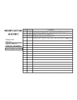
# No.

DATA

CONTENTS

#1

2000.3

Adds ten parts of exploded view owing to addition of the black model. (P.

5-1

24

)

#2

2000.10 Supply of LAMP UNIT was changed. (P.

5-1

)

#3

2000.10 Parts number clerical error correction. (P.

5-1

)

#4

2000.10 Information label was added by change in place of production.[Made in Taiwan        Thailand]

(P

.5-1

)

MODEL NAME :

CPD-M151

SERVICE MANUAL

PARTS No. : 9-978-665-02

MODIFICATION

HISTORY

* Blue characters are linking.

Summary of Contents for Multiscan CPD-M151

Page 1: ... 2000 10 Supply of LAMP UNIT was changed P 5 1 3 2000 10 Parts number clerical error correction P 5 1 4 2000 10 Information label was added by change in place of production Made inTaiwan Thailand P 5 1 MODEL NAME CPD M151 SERVICE MANUAL PARTS No 9 978 665 02 MODIFICATION HISTORY Blue characters are linking ...

Page 2: ... the stand Plug Play DDC DDC1 DDC2B Supplied accessories LCD monitor 1 Rear cover 1 Power cord 1 AC adapter 1 HD15 video signal cable 1 Macintosh adapter 1 Rubber pads 2 Windows Monitor Information Disk Utility Disk 1 Macintosh Utility Disk 1 Warranty card 1 These operating instructions 1 5 4 3 2 1 6 7 8 9 10 11 12 13 14 15 Pin No 1 2 3 4 5 6 7 Pin No 8 9 10 11 12 13 14 15 Signal Red Green Composi...

Page 3: ...YNC 2 2 3 2 4 3 3 6 6 3 3 V BP 36 33 16 35 23 21 39 29 29 28 30 V ACTIV 400 480 480 400 600 600 624 768 768 768 768 SYNC H V POLARITY N N N N N N N P P P P P N N N N N N P P N N Power Saving Function This monitor meets the power saving guidelines set by VESA and ENERGY STAR as well as the more stringent NUTEK If the monitor is connected to a computer or video graphics board that is VESA DPMS Displ...

Page 4: ...MPOSANTS IDENTIFIÉS PAR UNE TRAME ET UNE MARQUE SONT CRITIQUES POUR LA SÉCURITÉ NE LES REMPLACER QUE PAR UNE PIÈCE PORTANT LE NUMÉRO SPECIFIÉ LES RÉGLAGES DE CIRCUIT DONT L IMPORTANCE EST CRITIQUE POUR LA SÉCURITÉ DU FONCTIONNEMENT SONT IDENTIFIÉS DANS LE PRÉSENT MANUEL SUIVRE CES PROCÉDURES LORS DE CHAQUE REMPLACEMENT DE COMPOSANTS CRI TIQUES OU LORSQU UN MAUVAIS FONCTIONNEMENT EST SUSPECTÉ After...

Page 5: ...emoval 2 1 2 2 Cabinet Complete Assy Removal 2 1 2 3 A Board J Board and Inverter Removal 2 2 2 4 H Board Removal 2 2 2 5 LCD Panel and Lamp Unit Removal 2 3 3 ADJUSTMENTS 3 1 4 DIAGRAMS 4 1 Block Diagrams 4 1 4 2 Circuit Boards Location 4 4 5 EXPLODED VIEWS 5 1 Chassis 5 1 5 2 Packing Materials 22 ...

Page 6: ... sharp or abrasive items such as a ballpoint pen or screwdriver This type of contact may result in a scratched picture tube Clean the screen with a soft cloth If you use a glass cleaning liquid do not use any type of cleaner containing an antistatic solution or similar additive as this may scratch the screen s coating Transportation When you transport this monitor grip the bottom of the screen fir...

Page 7: ...as illustrated 25 7 Getting Started Getting Started F D ES GB I IBM PC AT or compatible computer HD15 video signal cable supplied to monitor output HD15 video signal cable supplied to monitor output Connecting to a Macintosh Use the supplied Macintosh adapter Connect the supplied Macintosh adapter to the computer before connecting the cable This adapter is compatible with Macintosh LC Performa Qua...

Page 8: ... screw driver Soft cloth to place under the LCD panel 1 Remove the screws from the fixing shaft of the stand 2 Place the monitor on the soft cloth with the LCD panel facing down and pull the stand out from the monitor 9 Getting Started Getting Started F D ES GB I 3 Connect the video signal cable and AC adapter cord to the monitor 4 Clamp the AC adapter cord 5 Press the rear cover against the part ...

Page 9: ... s instruction manual The color number may vary according to your computer or graphics board The color palette setting and the actual number of colors are as follows High color 16 bit n 65 536 colors True Color 24 bit n about 16 77 million colors In true color mode 24 bit speed may be slower 11 Getting Started Customizing Your Monitor F D ES GB I Customizing Your Monitor Before adjusting Connect t...

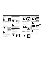
Page 10: ...Monitor Information Disk Utility Disk For Macintosh Macintosh Utility Disk 3 Start the Utility Disk and display the test pattern For Windows 95 98 Click Utility Disk n Windows n Utility exe For Macintosh Click Utility Disk n SONY Utility 4 Press the MENU button The MENU OSD appears 5 Press the buttons to select PITCH and press the MENU button again The PITCH OSD appears PITCH 0 AUTO MENU MENU MENU...

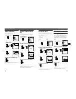
Page 11: ...color temperature so that it matches the actual colors of a printed picture Once the color temperature is adjusted it will be stored in memory for all input signals received 1 Press the MENU button The MENU OSD appears MENU MENU EXIT PHASE PITCH CENTER COLOR LANGUAGE OPTION MENU OK 15 Getting Started Customizing Your Monitor F D ES GB I 2 Press the buttons to select COLOR and press the MENU button...

Page 12: ... I Locking the Controls The control lock function disables all of the controls except the u power switch MENU and some other buttons Once you select LOCK you can select only the following items in the MENU OSD EXIT CONTROL LOCK and FACTORY PRESET in the OPTION OSD If you press any locked button the mark appears on the screen 1 Press the MENU button The MENU OSD appears 2 Press the buttons to selec...

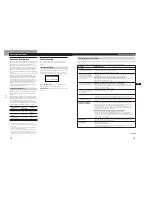
Page 13: ...e problem is caused by the connected computer or other equipment please refer to the connected equipment s instruction manual Use the self diagnosis function page 20 if the following recommendations do no resolve the problem Symptom Check these items No picture If the u indicator is not lit If the NO INPUT SIGNAL message appears on the screen or if the u indicator is either orange or alternating b...

Page 14: ...een 1 Disconnect the video signal cable 2 Before the monitor goes to power saving mode press the button and keep it pressed for 2 seconds If all four color bars appear white red green blue the monitor is working properly Reconnect the video signal cable and check the condition of your computer If the color bars do not appear there is a potential monitor failure Inform your authorized Sony dealer o...

Page 15: ...ion 1 Remove inside edges of back cover assembly with opening to direction of arrow 2 Ten claws 5 Three claws 4 Three claws 6 Remove the back cover assembly to direction of arrow 3 Three claws Handle with care to not break the claws A A A B B 1 Four screws 2 Three claws Cushion 3 Cabinet complete assy ...

Page 16: ...t tooth washer Three screws ext tooth washer 1 Four screws ext tooth washer 3 Cushion shield 4 A board 2 J board bracket 9 Inverter 7 J board 1 Chassis complete assy Be sure to confirm not upside down when install chassis complete assembly to beznet complete assembly Cushion 3 H board 2 Five lock Beznet complete assy ...

Page 17: ...CPD M151 2 5 LCD PANEL AND LAMP UNIT REMOVAL 2 3 2 Two screws 4 Two screws 1 Two screws CN3 CN2 J2 J1 3 LCD panel 5 Lanp unit ...

Page 18: ...tor The monitor internal DACs are read and shown on screen sliders A CONNECT icon would show up on the lower left corner of the dialog screen 3 An error message would pop up should communication fail A BREAK icon would show up on the dialog screen If this happens check the hardware setup communication cable and the connection Warm up time Allow 30 minutes warm up time before doing any adjust ment ...

Page 19: ...ent Color x y Y 40 IRE 9300 283 298 10 6500 314 328 10 5000 345 358 10 Tole 10 10 3 Geometry Adjustment 1 Connect the personal computer which has alignment data 2 Click Apply Default inside Geometry Register Box 3 Adjust Pitch for optinum screen performance 4 Adjust Phase for optinum screen performance 5 Adjust H position to make the screen center horizontally 6 Adjust V position to make the scree...

Page 20: ...ON LED ON LED STB EN 3V ADC PW OFF 12V OFF PANEL EN OVA GRN OVA BUF OVA FBK TCK VERT CLKH CLKL S CLK SENBLE SYNC HOLD V SYNC RGB SDA SDA SCL SCL CLAMP OUT H OUT H OUT V OUT H STATE V STATE V POL S DATA SER OUT TEST VKLT ADJ V REF U1 VERT S SIN GREEN IN COMP H IN VERT IN PLL SEN PLL SCLK PLL S DATA VCO CLK OUT H PLS OUT CLK IN COAST HS IN H SYNC RGB HP IN VS IN SYNC PHS SYNC SEL SCL SDA H STATE V S...

Page 21: ...2 5A D31 16 18 14 22 23 25 27 26 24 1 20 28 13 17 19 15 21 4 5 3 6 7 2 V IN BST 3 DH3 LX3 DL3 CS3 GND FB3 3 3V ON OFF 12V ON OFF EN 3V 12V OFF LXFY BSTFY DLFY CSP FBFY DHFY FB5 CS5 DL5 LX5 DH5 BST5 5V ON OFF VL U25 POWER CONTROL 12 V IN ON OFF V OUT CASE ADJ 1 3 5 4 U21 8V REG 2 J5 12V IN GND GND 12V IN V IN ON OFF V OUT CASE ADJ 1 2 3 4 6 U1 5V REG A 2 2 POWER TO A 1 2 1 TO AC ADAPTER 4 2 CIRCUIT...

Page 22: ...le numéro spécifié NOTE 10 11 1 12 2 13 4 5 6 7 8 9 14 15 15 1 A 1017 121 A BEZNET COMPLETE ASSY WHT 1 1 A 1017 226 A BEZNET COMPLETE ASSY BLK 2 1 803 808 11 PANEL LCD 2 3 1 418 666 11 LAMP UNIT 3 4 1 791 629 11 CABLE FLAT 5 1 418 667 11 INVERTER 6 A 1372 710 A H BOARD COMPLETE 7 A 1294 845 A A BOARD COMPLETE 8 A 1388 265 A J BOARD COMPLETE 9 A 1006 568 A CABINET COMPLETE ASSY WHT 1 9 A 1006 583 A...

Page 23: ...55 A 1501 730 A COVER ASSY STAND BLK 56 3 867 552 21 MANUAL INSTRUCTION WHT 1 56 3 867 552 31 MANUAL INSTRUCTION BLK 57 4 071 633 01 CUSHION LEFT 58 4 071 634 01 CUSHION RIGHT 59 4 073 804 01 INDIVIDUAL CARTON WHT 1 59 4 077 561 01 INDIVIDUAL CARTON BLK CPD M151 9 978 665 02 2000JL24253 1 Sony Corporation Computer Display Division Company Computer Display Div 9 978 665 02 English 2000JL24253 1 Pri...

Reviews: