


SECTION 2
ADJUSTMENTS
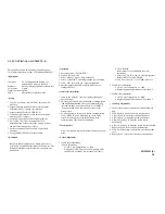
2-1. FUNCTIONAL ALIGNMENT (1)
• Procedures of how to go to service mode.
1. Hold “+” and “-” key power on, SDM-M
6
1 goes into service mode.
2. Press “MENU” key-----ODS display.
3. Press “-” key to go to second page’s late icon.
4. Press “OK” key-----service menu display.
5. Select one of features.
6. Press “MENU” key to exit OSD.
7. Power OFF then ON again, monitor go to normal mode.
If you would like to enter service mode again, performing the above procedures cycle.
Note
1. N/A means “Not applied”.
2. This service menu only provides both Configuration & Sync slice functions.
This other were used for design engineering. There is no guarantee of using those N/A functions.
PERFORM
(N/A)
(N/A)
(N/A)
(N/A)
(N/A)
(N/A)
INITIAL EE PRM
OK
ANALOG
CONFIGURATION
CHIPS
SYNC SLICE
TMDS
EXIT
(N/A)
(N/A)
COLOR TEMP
INITIAL EE PROM
CLEAR ETI TIME
PRESET B/C/C
EEPROM TEST
EXIT
9300K
6500K
5000K
BRT 1
CON 1
EXIT
9300K
6500K
5000K
BRT 2
CON 2
EXIT
SUB-BRIGHTNESS
R
G
B
SUB-CONTRAST
R
G
B
EXIT
●
On
☼
Off
DIGITAL
SDM-M61(E)
2-1
Summary of Contents for Multiscan SDM-M61
Page 5: ......
Page 6: ......
Page 7: ......
Page 8: ......
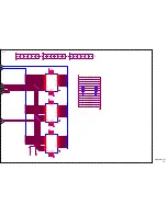
Page 15: ...A a 1 2 3 012 34 14 5 6 6 6 6 6 6 6 6 6 6 6 6 6 6 6 1 2 3 SDM M61 E 3 3 ...
Page 16: ...SDM M61 E 3 4 0 120 3 1 0 3 0 0 0 0 0 0 0 0 0 0 0 0 0 0 0 0 0 0 4 A b ...
Page 17: ... SDM M61 E 3 5 A c ...
Page 18: ...A d 0 1 2 2 1 1 2 2 1 3 3 SDM M61 E 3 6 ...
Page 19: ... A e SDM M61 E 3 7 ...
Page 20: ... 01 22 01 01 3 A f SDM M61 E 3 8 ...
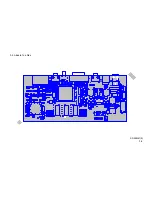
Page 21: ...3 9 A Board Top Side SDM M61 E 3 9 ...
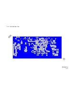
Page 22: ...3 10 A Board Bottom Side SDM M61 E 3 10 ...
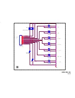
Page 23: ...POWER MENU CONTRAST BRIGHTNESS UP PLUS DOWN MINUS OK INPUT H TO A BOARD CN9 SDM M61 E 3 11 ...
Page 24: ...Input From M B s Amp Output To Speakers SDM M61 E J 3 12 ...
Page 25: ...3 13 H Board J Board H Board J Board SDM M61 E 3 13 ...