1-8
MVS-8000X/7000X
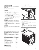
5. Close the both eject levers at a time, when the eject
lever claws reach the A position (
1
).
And push the eject levers (
2
) until the unlock buttons
pop out.
A
1
1
2 3
3 2
A
Eject lever
Eject lever
Eject lever
Unlock button
Unlock button
This figure shows MVS-8000X
1-4-2. Installing the Connector Board
Service Tool
Lever unlock jig : Part No. 4-193-124-01
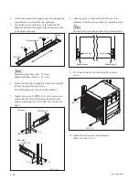
1. Insert the protrusion of the lever unlock jigs into the
red groove of the blank panel's rear levers (
1
) and
while pushing the lever unlock jigs, open the rear
levers outward to unlock.
1
1
Unlock button
Lever unlock jig
Lever unlock jig
Rear lever
Rear lever
Lever unlock jig
Blank panel
This figure shows MVS-8000X
Summary of Contents for MVS-8000X System
Page 4: ......
Page 54: ......
Page 58: ...Sony Corporation MVS 7000X SY MVS 8000X SY E 4 189 509 03 Printed in Japan 2011 5 08 2010 ...


