1-14
MVS-8000X/7000X
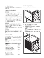
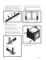
4. Loosen the screws on the rear of the right and left
adapters and adjust the length of the adapter according
to the depth of the rack.
(The
fi
gure bellow shows the left adapter.)
Adapter
Portion of
the rail
B4
x
6
B4
x
6
n
Maximum depth of adapter: 750 mm
Minimum depth of adapter: 595 mm
5. Attach the right and left adapters to the rack complete-
ly using the speci
fi
ed six screws.
(The
fi
gure bellow shows the left adapter.)
B4
x
10
31.75
31.75
1U
4U
8U
Unit : mm
B4
x
10
6. Tighten the screws (B4
x
6: two screws each on the
right and left) for adjusting the length of the adapter
completely (the screws that were loosened in step 4).
7. Align the groove of the rack tool at the side of the
equipment with the rail, and slide the equipment to the
rear.
n
The rack tools are hooked on the rails as shown below.
Rack tool
Rail
Rail
Rack tool
8. Fix the rack angle in the rack using the speci
fi
ed
screws.
+B5
x
12
+B5
x
12
9. Attach the front panel to the equipment.
(Refer to Section 1-4-1.)
Summary of Contents for MVS-8000X System
Page 4: ......
Page 54: ......
Page 58: ...Sony Corporation MVS 7000X SY MVS 8000X SY E 4 189 509 03 Printed in Japan 2011 5 08 2010 ...

