1-23
MVS-8000X/7000X
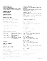
D13 (N-2) : GbE2
Lights when linked Ethernet 2 on CPU-DP module.
Not used on this board.
D14 (N-2) : SGMII1
Lights when linked SGMII 1 on CPU-DP module.
This board supports Ethernet connections for internal
communications.
D15 (N-2) : SGMII2
Lights when linked SGMII 2 on CPU-DP module.
Not used on this board.
D16 (L-6) : 3.3 V_LV
Power supply status indication.
Lights when
+
3.3 V power is supplied normally.
D17 (L-4) : 1.8 V_PHY
Power supply status indication.
Lights when
+
1.8 V power is supplied normally to the
PHY on CPU-DP module.
< Switch on the CPU-DP Module >
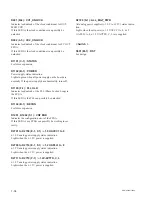
SW2 (P-2) : CPU-DP MODE
Sets the start-up mode of CPU-DP module.
Default setting when shipped from the factory is all OFF.
< LED on the SG-272 board >
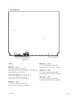
D100 (B-1) : REF OK status LED
Lights when detected the V-sync of the reference input.
D101 (B-1) : REF EXT status LED
Lights when the synchronize signal input to the reference
input.
D200 (B-1) : LOCK status LED
Lights when synchronized to the reference signal.
< LED on the SIO-26 board >
D200 (A-3) : Communication error indication
Lights when the communication error is occurred through
the Editor port or the Serial Tally port.
D201 (A-3) : Communication status indication
Blinks when communicating through the Editor port.
D202 (A-3) : Communication status indication
Blinks when communicating through the Serial Tally port.
< Switch on the SIO-26 board >
S300 (A-3) : Switch for production
Used only for production in the assembly factory. Do not
change the setting.
Default setting when shipped from the factory is all OFF.
S500 (A-2) : Reset switch
Initializes the SIO-26 board.
Summary of Contents for MVS-8000X System
Page 4: ......
Page 54: ......
Page 58: ...Sony Corporation MVS 7000X SY MVS 8000X SY E 4 189 509 03 Printed in Japan 2011 5 08 2010 ...


