1-36
MVS-8000X/7000X
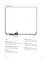
D1107 to D1122 (N-1, P-1) : CPU status LED
CPU status indication.
D1301 (M-1) : INET LINK
Ethernet communication status indication for internal
communications.
Lights when linked.
D1302 (M-1) : INET ACT
Ethernet communication status indication for internal
communications.
Blinks when data receiving/transmitting.
< Switch >
S501 (J-1) : RST
Pressing this switch initializes the board.
S701 (K-1) : MON
The reset switch that is used to reset the monitor during
maintenance through the terminal. (Valid only for the
XPT-31 board)
S1102 (J-1) : CPU RESET
Pressing this switch initializes only the CPU on the circuit
board. (Valid only for the XPT-31 board)
< LED on the CPU-DP Module >
Refer to < LED on the CPU-DP module > in “1. CA-82
board”.
(CPU-DP is installed only on the XPT-31 board.)
< Switch on the CPU-DP Module >
Refer to < Switch on the CPU-DP module > in “1. CA-82
board”.
(CPU-DP is installed only on the XPT-31 board.)
Summary of Contents for MVS-8000X System
Page 4: ......
Page 54: ......
Page 58: ...Sony Corporation MVS 7000X SY MVS 8000X SY E 4 189 509 03 Printed in Japan 2011 5 08 2010 ...


