1-43
MVS-8000X/7000X
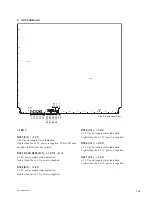
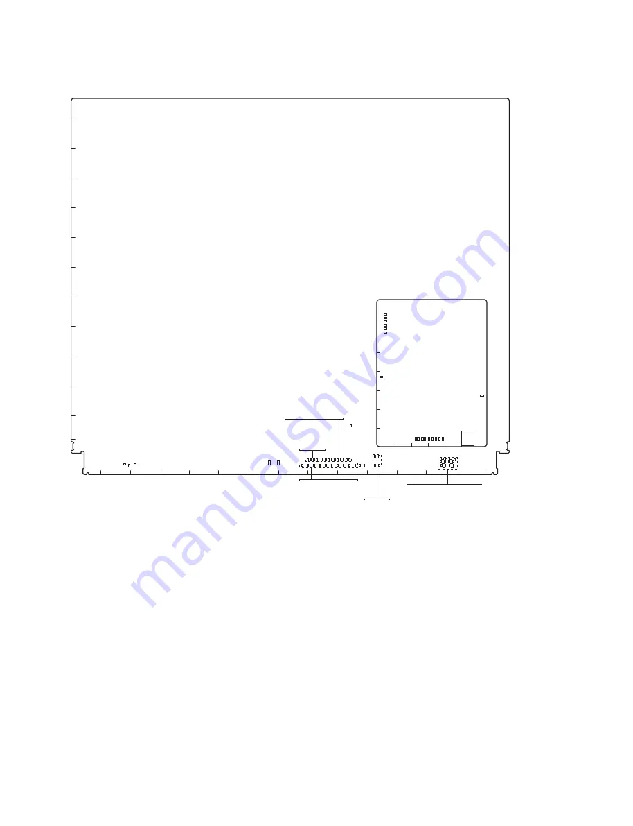
10. DVP-53 Board
12
13
11
10
9
8
7
6
5
4
3
2
1
A
B
C
D
E
F
G
H
J
K
L
M
N
P
R
D719
D721
D718
D705
D713
D708
D716
D702
D710
D706
D203
D903
D901
D904
D902
D308
D307
D304
D402
D403
D405
D407
D305
D306
D302
D303
D309
D301
D720 D1510
D704
D714
D712
D717
D709
D707
D703
D715
D71
1
CPU-DP
Module
6
5
4
3
2
1
A
B
C
D
E
F
G
H
D1
D3
D5
D2
D4
D16
D17
D1
1
D10
D9
D8
D7
D15 D14 D13 D12
D6
SW2
Side A (Component Side)
S501
S801
D701
D1509
D1502
D1501
D1503
D1506
D1507
D1504
D1505
D1508
D501
< LED >
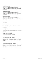
D719 (B-1) : POWER
Power supply status indication.
Lights in green when all power supply on the board are
normally.
D203 (H-1) :
+
12 V
+
12 V power supply status indication.
Lights when the
+
12 V power is supplied. If this LED does
not light, the fuse may have blown.
D301 (K-1) :
+
1.0 V
+
1.0 V power supply status indication.
Lights when the
+
1.0 V power is supplied.
D302, D303, D309 (K-1) :
+
1.1 V-1, -2, -3
+
1.1 V power supply status indication.
Lights when the
+
1.1 V power is supplied.
D304, D305, D306 (J-1) :
+
1.8 V-1, -2, -3
+
1.8 V power supply status indication.
Lights when the
+
1.8 V power is supplied.
D307 (J-1) :
+
2.5 V
+
2.5 V power supply status indication.
Lights when the
+
2.5 V power is supplied.
Summary of Contents for MVS-8000X System
Page 4: ......
Page 54: ......
Page 58: ...Sony Corporation MVS 7000X SY MVS 8000X SY E 4 189 509 03 Printed in Japan 2011 5 08 2010 ...


