USO
RESTRITO
Signal Selection
93
Button
Number when the
shift button is not
pressed
Number when the
shift button is
pressed
Reentry buttons
121 to 123
125 to 127
Button
Number when the
shift button is not
pressed
Number when the
shift button is
pressed
From the left end
to the 31st button
1 to 31
32 to 62
Reentry buttons
121 to 124
125 to 128
Button
Button
Button numbers
1st row
From the left end to the 31st
button
1 to 31
Reentry buttons
121 to 124
2nd row
From the left end to the 31st
button
32 to 62
Reentry buttons
125 to 128
Ch
a
p
te
r 3
S
ig
n
a
l S
e
le
c
ti
o
n
and
T
ra
n
s
itio
n
s
Notes
Cross-point control block button numbers
For details of the [SIDE FLAG] button, see “Assigning a
Cross-Point Button to Enable/Disable Side Flags” in
Chapter 19 (Volume 2).
Switching button numbers
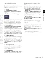
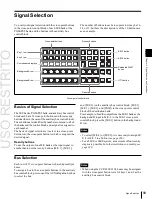
The rightmost (32nd) button functions as a shift button
(the shift button function can be disabled in the Setup
menu).
You can use the rightmost button (number 32) as a [SIDE
FLAG] button. In this case, the shift button moves one to
the left, to number 31, and the button numbers are offset by
one.
When selecting the signals of button numbers 1 to 31,
press the cross-point button for the desired signal.
To select button numbers 32 to 62, hold down the shift
button, and press the cross-point button for the desired
signal.
Button numbers in the auxiliary bus control block
2ND button
(1st row)
(2nd row)
When the [2ND] button is unlit
The cross-point buttons and reentry buttons in the auxiliary
bus control block have separate upper (1st row) and lower
(2nd row) numbers.
In the case of a 32-button layout, the button numbers are as
follows.
Auxiliary bus control block button numbers ([2ND] button unlit)
Auxiliary bus control block button numbers ([2ND] button lit)
When the [2ND] button is lit
Different buses can be assigned to the 1st-row buttons and
2nd-row buttons. When the 32nd button is set as a shift
button, the 1st-row buttons and 2nd-row buttons both have
the following button numbers.
Inhibiting cross-point button operations
For each cross-point button, you can temporarily inhibit
operations.
Notes
This setting is cleared when you reset the control panel.
Assigning a button to the function of disabling cross-
point button operation
You can assign the button to be used for the operation to
the [PRE MCRO] button, in setup.
For details, see “Overall Control Panel Settings (Config
Menu)” in Chapter 19 (Volume 2).
Summary of Contents for MVS-8000X SystemMVS-7000X System
Page 358: ...USO RESTRITO 358 Wipe Pattern List Appendix Volume 1 Enhanced Wipes Rotary Wipes ...
Page 360: ...USO RESTRITO Random Diamond DustWipes 360 1 w pe PaternLO ...
Page 362: ...USO RESTRITO 362 DME Wipe Pattern List Appendix Volume 1 Door 2D trans 3D trans ...
Page 364: ...USO RESTRITO 364 DME Wipe Pattern List Appendix Volume 1 Page turn Page roll ...
Page 377: ...USO RESTRITO Menu Tree 377 Appendix Volume 1 AUX Menu AUX button CCR Menu CCR button ...
Page 379: ...USO RESTRITO Menu Tree 379 Appendix Volume 1 DME Menu DME button ...
Page 381: ...USO RESTRITO Menu Tree 381 Appendix Volume 1 Macro Menu MCRO button ...
Page 382: ...USO RESTRITO 382 Menu Tree Appendix Volume 1 Key Frame Menu KEY FRAME button ...
Page 383: ...USO RESTRITO Menu Tree 383 Appendix Volume 1 Effect Menu EFF button ...
Page 384: ...USO RESTRITO 384 Menu Tree Appendix Volume 1 Snapshot Menu SNAPSHOT button ...
Page 385: ...USO RESTRITO Menu Tree 385 Appendix Volume 1 Shotbox Menu SHOTBOX button ...
Page 386: ...USO RESTRITO 386 Menu Tree Appendix Volume 1 File Menu FILE button ...
Page 391: ...USO RESTRITO Menu Tree 391 Appendix Volume 1 ENG SETUP button to previous pages ...
Page 413: ...USO RESTRITO MVS 8000X System MVS 7000X System SY 4 470 637 01 1 Sony Corporation 2013 ...
Page 706: ...USO RESTRITO MVS 8000X System MVS 7000X System SY 4 470 637 01 1 Sony Corporation 2013 ...


