USO
RESTRITO
System Settings (System Config Menu)
547
Ch
a
p
te
r 18
S
y
s
te
m
S
e
tu
p
(S
y
s
te
m
)
System Settings (System
Config Menu)
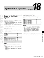
To make the system settings, use the System >System
Config menu.
Specify the overall system operation mode and the
hierarchical relationship of the devices.
To display the System Config menu
In the Engineering Setup menu, select VF1 ‘System’ and
HF2 ‘System Config.’
Notes
After changing the following settings, be sure to press
[Execute] to save the new values. If you want to cancel the
setting changes without saving them, press [Clear].
Device operating mode selection
The operating mode determines how many switcher and
DME units can be controlled from the control panel.
Device hierarchical relationship setting
•
Panel Assign:
Specify the switcher controlled by a
control panel.
•
Switcher Assign:
Specify the DME connected to a
switcher.
Selecting the System Operation
Mode
In the <Operation Mode> group of the System >System
Config menu, select one of the following.
•
Single Proc mode:
The control panel controls a single
switcher and DMEs.
•
Dual Simul mode:
The control panel controls two
switchers and DMEs simultaneously. Also, it allows
operation to continue on one switcher if the other
switcher cannot communicate due to device failure or
other cause.
Notes
Dual Simul mode cannot be selected if the signal format is
1080P or if it is set to 3D mode.
Selecting a system to set to Dual Simul
mode
In Dual Simul mode, a target system must be selected in
order to configure the two switchers and the DMEs
connected to the switchers.
In the <Target System> group, press [System 1] or
[System 2], turning it on. You can also turn both systems
on and configure them simultaneously.
Specifying the Switcher Controlled
by the Control Panel
The number of control panels that can be connected to a
single switcher depends on the signal format setting.
1080P:
2
Other than 1080P:
4
1
In the System >System Config menu, press [Panel
Assign].
The Panel Assign menu appears.
2
Select the switcher to be controlled by the selected
control panel, as follows.
If there is only one switcher on the network:
In the
<1st Switcher> group, set either [SWR1] or
[SWR2] to On to select the switcher to be
operated.
In the <2nd Switcher> group, set both [SWR1]
and [SWR2] to Off.
If there are two switchers on the same network:
In
the <1st Switcher> group and <2nd Switcher>
group, select the switcher to be operated.
When the system operation mode (see previous
item) is set to [Dual Simul], the switcher status set
in <1st Switcher> appears on the control panel.
3
To set the selected control panel as tally control master
panel, press [Tally Master], turning it on.
If there are multiple panels and processors, the control
panel for which [Tally Master] is set to On carries out
tally control for the whole system.
Notes
•
When there are multiple control panels, make sure
that one of them has [Tally Master] set to On. When
you change the master panel, be sure to copy and
save the setup tally (TLY) and router (RTR) data in
the File menu, and make the same settings for other
panels.
•
If you load the master panel tally data into a panel
with a different unit ID, then [Tally Master] changes
to Off.
To select the lighting mode of the switcher bus
selection buttons on the remote panel
When switching buses with the MKS-8080/8082 AUX
Bus Remote Panel or other remote panel connected via S-
Summary of Contents for MVS-8000X SystemMVS-7000X System
Page 358: ...USO RESTRITO 358 Wipe Pattern List Appendix Volume 1 Enhanced Wipes Rotary Wipes ...
Page 360: ...USO RESTRITO Random Diamond DustWipes 360 1 w pe PaternLO ...
Page 362: ...USO RESTRITO 362 DME Wipe Pattern List Appendix Volume 1 Door 2D trans 3D trans ...
Page 364: ...USO RESTRITO 364 DME Wipe Pattern List Appendix Volume 1 Page turn Page roll ...
Page 377: ...USO RESTRITO Menu Tree 377 Appendix Volume 1 AUX Menu AUX button CCR Menu CCR button ...
Page 379: ...USO RESTRITO Menu Tree 379 Appendix Volume 1 DME Menu DME button ...
Page 381: ...USO RESTRITO Menu Tree 381 Appendix Volume 1 Macro Menu MCRO button ...
Page 382: ...USO RESTRITO 382 Menu Tree Appendix Volume 1 Key Frame Menu KEY FRAME button ...
Page 383: ...USO RESTRITO Menu Tree 383 Appendix Volume 1 Effect Menu EFF button ...
Page 384: ...USO RESTRITO 384 Menu Tree Appendix Volume 1 Snapshot Menu SNAPSHOT button ...
Page 385: ...USO RESTRITO Menu Tree 385 Appendix Volume 1 Shotbox Menu SHOTBOX button ...
Page 386: ...USO RESTRITO 386 Menu Tree Appendix Volume 1 File Menu FILE button ...
Page 391: ...USO RESTRITO Menu Tree 391 Appendix Volume 1 ENG SETUP button to previous pages ...
Page 413: ...USO RESTRITO MVS 8000X System MVS 7000X System SY 4 470 637 01 1 Sony Corporation 2013 ...
Page 706: ...USO RESTRITO MVS 8000X System MVS 7000X System SY 4 470 637 01 1 Sony Corporation 2013 ...


