USO
RESTRITO
640
Setup Relating to DCU / Settings Relating to Parallel Inputs (Input Config Menu)
Ch
a
p
te
r 22
DCU
S
e
tu
p
(
DC
U)
DCU Setup (DCU)
Chapter
22
Setup Relating to DCU
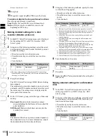
In DCU setup, carry out settings particular to the DCU.
You can make the following settings.
•
Input Config:
Assign GPI inputs to Parallel input ports.
•
GPI Input Assign:
Make GPI input settings.
•
Output Config:
Assign GPI outputs to parallel output
ports inserted in an option slot.
•
GPI Output Assign:
Make GPI output settings.
•
Serial Port Assign:
Set the protocol to match the
devices connected to a 9-pin serial port. You can also
select the control panel used to control each device.
Notes
For setup relating to DCU, it is necessary to make the same
settings on multiple control panels (maximum three units)
that are sharing the DCU. After carrying out the DCU
setup on one control panel, make the same settings on the
other control panels.
Settings Relating to
Parallel Inputs (Input
Config Menu)
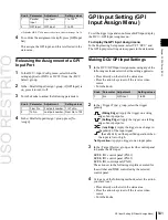
To assign GPI inputs to DCU parallel input ports, display
the DCU >Input Config menu.
The DCU parallel input ports are assigned with the
following priority sequence.
1.
When external boxes are set in the Router/Tally
>Router >External Box Assign menu, the parallel inputs
are assigned to the external box inputs in order.
2.
When tally settings are carried out in the Router/Tally
>Tally Enable menu, tally inputs are assigned
automatically.
In this menu, you set only the input ports which are unused
after making the above assignments.
To display the Input Config menu
In the Engineering Setup menu, select VF5 ‘DCU’ and
HF1 ‘Input Config.’
The status area shows input port information.
Assigning a GPI Input Port
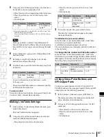
1
In the DCU >Input Config menu, select what the
setting applies to (DCU1 or DCU2) from the <DCU
Select> group.
2
In the <Parallel Input Assign> group, press [GPI
Input].
3
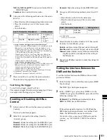
Using any of the following methods, assign the
number of the GPI input to the input port.
•
Press directly on the list in the status area.
•
Press the arrow keys to scroll the reverse video
cursor.
•
Turn the knobs.
Summary of Contents for MVS-8000X SystemMVS-7000X System
Page 358: ...USO RESTRITO 358 Wipe Pattern List Appendix Volume 1 Enhanced Wipes Rotary Wipes ...
Page 360: ...USO RESTRITO Random Diamond DustWipes 360 1 w pe PaternLO ...
Page 362: ...USO RESTRITO 362 DME Wipe Pattern List Appendix Volume 1 Door 2D trans 3D trans ...
Page 364: ...USO RESTRITO 364 DME Wipe Pattern List Appendix Volume 1 Page turn Page roll ...
Page 377: ...USO RESTRITO Menu Tree 377 Appendix Volume 1 AUX Menu AUX button CCR Menu CCR button ...
Page 379: ...USO RESTRITO Menu Tree 379 Appendix Volume 1 DME Menu DME button ...
Page 381: ...USO RESTRITO Menu Tree 381 Appendix Volume 1 Macro Menu MCRO button ...
Page 382: ...USO RESTRITO 382 Menu Tree Appendix Volume 1 Key Frame Menu KEY FRAME button ...
Page 383: ...USO RESTRITO Menu Tree 383 Appendix Volume 1 Effect Menu EFF button ...
Page 384: ...USO RESTRITO 384 Menu Tree Appendix Volume 1 Snapshot Menu SNAPSHOT button ...
Page 385: ...USO RESTRITO Menu Tree 385 Appendix Volume 1 Shotbox Menu SHOTBOX button ...
Page 386: ...USO RESTRITO 386 Menu Tree Appendix Volume 1 File Menu FILE button ...
Page 391: ...USO RESTRITO Menu Tree 391 Appendix Volume 1 ENG SETUP button to previous pages ...
Page 413: ...USO RESTRITO MVS 8000X System MVS 7000X System SY 4 470 637 01 1 Sony Corporation 2013 ...
Page 706: ...USO RESTRITO MVS 8000X System MVS 7000X System SY 4 470 637 01 1 Sony Corporation 2013 ...


