5
MZ-E10
SECTION 3
DISASSEMBLY
Note :
Follow the disassembly procedure in the numerical order given.
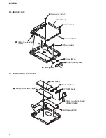
3-1. PANEL ASSY (S), UPPER
r
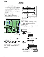
The equipment can be removed using the following procedure.
6
4
1
Two screws (M1.4)
7
Panel ASSY (S), upper
2
Claw
Holder ASSY
3
Claw
5
Bracket ASSY
Panel ASSY (S), upper
Set
Optical pick-up ASSY
(ABX-1ES)
Mechsnism deck
(MT-MZE10-184)
Bracket ASSY
POWER board, MAIN board
CONTROL board
3-2. MECHANISM DECK (MT-MZE10-184)
3
1
Screw, step
6
Mechanism deck
(MT-MZE10-184)
4
OP flexible board
(CN501)
2
Two claws
5
Motor flexible board
(CN551)
Summary of Contents for MZ-E10
Page 39: ...39 MZ E10 MEMO ...

