– 19 –
– 20 –
***
: NG item number.
8. If OK through the overall MO adjustments, press the
x
key
to return to the test mode and terminate the Overall Adjustment
mode.
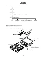
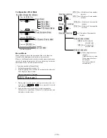
Overall Adjustment Mode
• Configuration of overall adjustment
N
>
key
.
key
Overall adjustment mode
(Title display)
CD overall
adjusting
CD overall
adjustment
OK
MO overall
adjusting
MO overall
adjustment
OK
CD overall
adjustment
NG
MO overall
adjustment
NG
All item
OK
NG item exists
or
x
key
NG item exists
or
x
key
x
key
x
key
x
key
x
key
[Test mode $display check mode%]
N
>
key
Note:
Adjust the CD first, when performing adjustment.
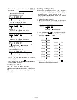
6. Insert MO disc in the set, and press the
N
>
key to set the
Overall MO Adjustment mode. Automatic adjustments are
made.
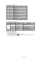
• Overall CD and MO adjustment items
1. Overall CD adjustment items
Item No.
Description
312
313
CD electrical offset adjustment
314
328
CD TWPP gain adjustment
321
CD tracking error gain adjustment
323
CD tracking error offset adjustment
332
336
CD ABCD level adjustment
344
CD focus gain adjustment
345
CD tracking gain adjustment
521
CD two-axis sensitivity adjustment
522
341
CD focus bias adjustment
XXX
MO RUN
Remote commander LCD display
XXX: Item number for which an adjustment is being executed.
7. If NG in the overall MO adjustments, return to NV reset (see
page 17) and perform the adjustment again.
000
***
NG
Remote commander LCD display
000
MO OK
Remote commander LCD display
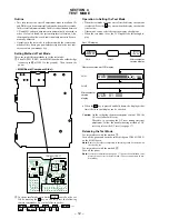
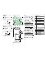
TP902 (BATT –)
TP918
(VC)
TP903
(2V IN)
TP919
(VR)
TP901
(BATT +)
TP904
(SET GND)
– MAIN Board (Conductor side) –
• Adjustment method of normal charging current
(item number 721)
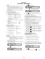
1. Select the manual mode of the test mode, and set item number
721 (see page 13).
2. Connect a digital voltmeter between TP901 (BATT+) and
TP902 (BATT-) on the MAIN board, and adjust with
[VOL +]
key (voltage up) or
[VOL --]
key (voltage down) so that the
voltage becomes 1.236
±
0.036 V.
If the voltage is already adjusted, go to the next adjustment
item without pressing the
X
key.
3. Press the
X
key to write the adjusted value.
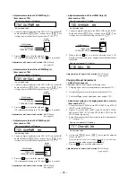
• Adjustment method of trickle charging current
(item number 722)
1. Select the manual mode of the test mode, and set item number
722 (see page 13).
2. Connect a digital voltmeter between TP901 (BATT+) and
TP902 (BATT-) on the MAIN board, and adjust with
[VOL +]
key (voltage up) or
[VOL --]
key (voltage down) so that the
voltage becomes 0.168
V.
If the voltage is already adjusted, go to the next adjustment
item without pressing the
X
key.
3. Press the
X
key to write the adjusted value.
721
ChgPW1 **
Remote commander LCD display
**
: Adjusted value
digital
voltmeter
MAIN board
TP901 (BATT +)
TP902 (BATT –)
722
ChgPW2 **
Remote commander LCD display
**
: Adjusted value
+0.036
–0
digital
voltmeter
MAIN board
TP901 (BATT +)
TP902 (BATT –)
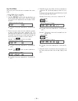
• Adjustment Method of Overall CD and MO Adjustment
Mode
1. Setting the test mode (see page 12).
2. Press the
[VOL --]
key activates the overall adjustment mode.
000
Assy11
Remote commander LCD display
3. Insert CD disc in the set, and press the
.
key to set the
Overall CD Adjustment mode. Automatic adjustments are made.
XXX: Item number for which an adjustment is being executed.
4. If NG in the overall CD adjustments, return to NV reset (see
page 17) and perform the adjustment again.
XXX
CD RUN
Remote commander LCD display
000
***
NG
Remote commander LCD display
***
: NG item number.
5. If OK through the overall CD adjustments, then perform over-
all MO adjustments.
000
CD
OK
Remote commander LCD display
2. Overall MO adjustment items
Item No.
Description
112
113
MO electrical offset adjustment
114
118
221
Low reflective CD tracking error gain adjustment
223
Low reflective CD tracking error offset adjustment
232
236
Low reflective CD ABCD level adjustment
244
Low reflective CD focus gain adjustment
245
Low reflective CD tracking gain adjustment
121
MO tracking error gain adjustment
122
MO tracking error offset adjustment
134
MO TWPP gain adjustment
131
MO TWPP offset adjustment
132
136
MO ABCD level adjustment
144
MO focus gain adjustment
145
MO tracking gain adjustment
141
MO focus bias adjustment
Adjustment and Connection Location:

