background image

MZ-N707

33

33

VC B+

F801

F

RMC KEY

RVDD
DTCK

KEY-R
RGND

(LINE IN JACK)

OPTICAL

RECEIVER 

J302

i

J301

LINE IN

(OPTICAL)

J303

MIC

(PLUG IN POWER)

 SIGNAL PATH

: PLAYBACK

: REC (ANALOG IN)

: REC (DIGITAL IN)

3

12

14

9

1

2

24

4

23

22

21

15

17

49

69

93

XHP

STBY

37

58

36

38

198

151

197

45

46

47

1

71

2

3

4

B+ SWITCH

Q302

VIF B+

REGULATOR

MUTING

MIC AMP

IC303

IN1

IN2

STBY

OUT2

OUT1

HP/LINE
SWITCH

HEADPHONE AMP

IC302

OUT L

OUT R

OUTB BEEP

OUTA BEEP

IN L

IN R

HP/L

MUTE

BEEP

BEEP

MUTE

XJAC DET

XOPT CTL

FS256

XBCK

OSCO

OSCI

XCS NV1

SDI0

SCK0

SDO0

OPT DET

XMIC DET

RMC DTCK

SYSTEM CONTROLLER,

DIGITAL SIGNAL PROCESSOR,

16M BIT D-RAM

IC801 (2/3)

150

X801

45.1584MHz

SI0

SO0

SCK0

SDI0

SDO0

SCK0

SCK0

SDO0

AOUTL,
AOUTR

ADDT

DIN1

SDO0, SCK0

XCS

SK

DI

DO

B

A

C

E

EEPROM

IC804

2

4

1

3

10

15

14

13

9

GAIN

AMP

CLOCK

DIVIDER

AUDIO

I/F

CONTROL

CONTROL

REGISTER

I/F

A/D

CONVERTER

&

HPF

RIN1

RIN2

LIN1

LIN2

A/D CONVERTER

IC301

SDTO

CCLK

CSN

CDTI

12

LRCK

BCLK

16

PDN

11

MCLK

196

LRCK

148

XPD ADC

147 XCS ADC

AOUTL

AOUTR

18

120

13

REFERENCE

VOLTAGE

SWITCHING

Q301

VREF IN

+

(Page 32)

(Page 32)

(Page 34)

(Page 32)

(Page 34)

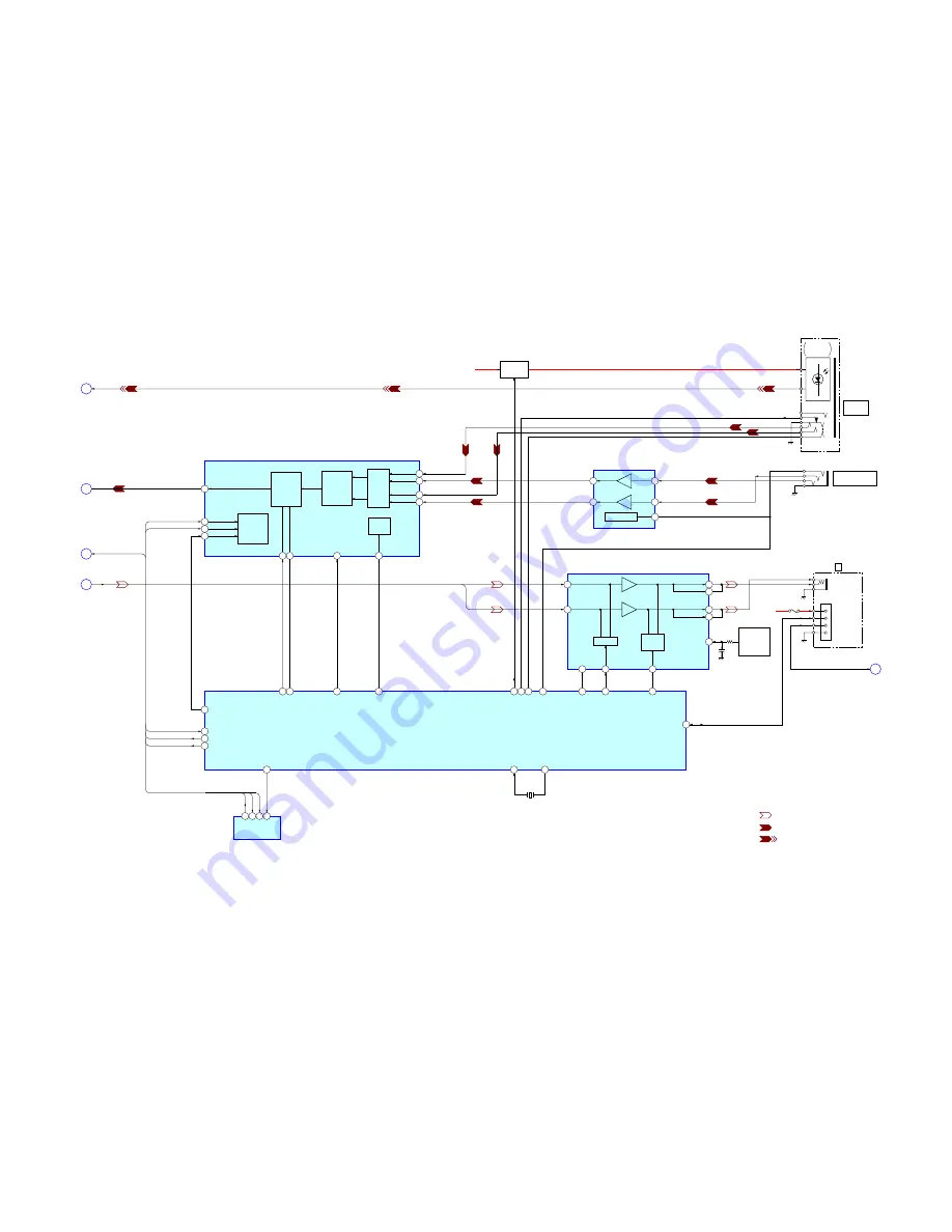
6-2.

BLOCK  DIAGRAM  – AUDIO Section –

Summary of Contents for MZ-N707 OpenMG Jukebox NOTES on installing & operating

Page 1: ...C AT are registered trademarks of International Business Machines Corporation Macintosh is a trademark of Apple Computer Inc in the United States and or other countries All other trademarks are trademarks of their respective owners and marks are omitted in this manual MD Recorder Audio playing system MiniDisc digital audio system Laser diode properties Material GaAlAs MQW Wavelength λ 790 nm Emiss...

Page 2: ...ITA3 1 The battery life may be shorter due to operating conditions the temperature of the location and varieties of batteries 2 When you record use a fully charged rechargeable battery Recording time may differ according to the alkaline batteries 3 Measured in accordance with the JEITA Japan Electronics and Information Technology Industries Association standard Batteries SP Stereo LP2 Stereo LP4 S...

Page 3: ...ism Deck Section 2 MT MZN707 177 59 8 ELECTRICAL PARTS LIST 60 CAUTION Use of controls or adjustments or performance of procedures other than those specified herein may result in hazardous ra diation exposure Notes on chip component replacement Never reuse a disconnected chip component Notice that the minus side of a tantalum capacitor may be dam aged by heat Flexible Circuit Board Repairing Keep ...

Page 4: ...ws 2000 Professional Windows XP Home Edition or Windows XP Professional manufacturer installed is supported only when used with the standard factory settings This software is not supported by the following environments Windows 95 Windows NT or other versions of Windows NT such as Server An environment that is an upgrade of the original manufacturer installed operating system as in the following ex...

Page 5: ... standby mode E Battery level indication Shows approximate battery condition F Disc indication Shows that the disc is rotating for recording playing or editing an MD G Time display H Group indication Lights up when group mode is on I Play mode indication Shows play mode of the MD J Level meter Shows the volume of the MD being played or recorded K REC REMAIN REMAIN remaining time tracks indication ...

Page 6: ...177 Page 8 3 6 SET CHASSIS 5192 ASSY Page 9 3 7 MAIN BOARD Page 9 3 8 OP SERVICE ASSY LCX 5R Page 10 3 9 HOLDER ASSY Page 11 3 10 DC MOTOR SLED M602 Page 11 3 11 DC SSM18B MOTOR SPINDLE M601 DC MOTOR OVER WRITE HEAD UP DOWN M603 Page 12 SET SECTION 3 DISASSEMBLY This set can be disassembled in the order shown below 3 1 DISASSEMBLY FLOW ...

Page 7: ...screws M1 4 1 two screws M1 4 2 Remove the case lower in the direction of the arrow 3 two screws M1 4 5 torsion spring pop up L 3 two screws M1 4 2 Slide the open slider in the direction of the arrow and open the upper panel section set chassis 5192 assy torsion spring pop up L 1 flexible board CN801 4 upper panel section ...

Page 8: ...on spring button Note On installation adjust the position of both switch and knob hold 4 button control A knob hold switch 5 upper panel sub assy 3 two step screws MD 6 mechanism deck MT MZN707 177 5 flexible board optical pick up CN501 4 2 flexible board motor CN502 1 Remove two solders of the flexible board over write head ...

Page 9: ...9 MZ N707 3 6 SET CHASSIS 5192 ASSY 3 7 MAIN BOARD 2 two screws 1 7 2 5 3 set chassis 5192 assy 1 four screws M1 4 2 4 battery case 5 main board 3 battery terminal 2 battery terminal board ...

Page 10: ... screw M1 4 6 thrust detent spring 8 Pull off lead screw 7 over write head section OP service assy LCX 5R 9 Opening the over write head toward the direction A remove the OP service assy LCX 5R toward the direction B A B Note Do not open the entire assy forcibly when opening the over write head ...

Page 11: ...OLDER ASSY 3 10 DC MOTOR SLED M602 4 holder assy 3 boss 3 boss 1 convex portion 2 Open the holder assy 2 washer 0 8 2 5 5 DC motor sled M602 4 two screws M1 4 3 gear SA 1 Remove six solders of the motor flexible board ...

Page 12: ...tapping screws 2 tapping screw 3 motor cover 6 gear HA 4 gear HB 5 gear HC DC motor over write head up down M603 3 15 mm gear HA Note Press fit the gear HA up to the position of the DC motor over write head up down M603 as shown below 7 DC motor over write head up down M603 1 Remove six solders of the motor flexible board ...

Page 13: ...tem displays its location Also the manual mode allows each individual adjustment to be auto matically adjusted Operation in the test mode is performed with the set A key having no particular description in the text indicates a set key SETTING METHOD OF TEST MODE There are three different methods to set the test mode 1 Short SL801 TEST on the MAIN board with a solder bridge connect pin zvn of IC801...

Page 14: ...nt OP Alignment Adjustment Overall Adjustment Mode Sound Skip Check Result Display Mode Key Check Mode Test Mode Display Check Mode Press the x CHG key Press the or VOL key Press the N or REC key Press the or VOL key Electrical Offset Adjustment Power Supply Adjustment Auto Item Feed CD Overall Adjustment MO Overall Adjustment Self Diagnosis Result Display Mode Press the MENU key Press the T MARK ...

Page 15: ... in which if an error occurred during the recording or playing the mechanism control block and the power supply control block in the microcomputer detect it and record its cause as history in the nonvolatile memory By checking this history in the test mode you can analyze a fault and determine its location Total recording time is recorded as a guideline of how long the optical pickup has been used...

Page 16: ...f code Simple display Description No error 00 No error No error 01 Illegal access target Adrs Attempt to access an abnormal address address was specified Servo system error 02 High temperature Temp High temperature detected 03 Focus error Fcus Disordered focus or can not read an address 04 Spindle error Spdl Abnormal rotation of disc TOC error 11 TOC error TOC Faulty TOC contents 12 Data reading e...

Page 17: ...3 2 Press the N key or REC key and the playing or recording sound skip result display mode becomes active respectively where the LCD displays the following 3 When the N key is pressed total error count is displayed on the LCD and each time the key is pressed the display item moves down by one as shown below Also if the key is pressed the display item moves up by one then if the REC key is pressed ...

Page 18: ...d as OK Example2 When the keys on the remote commander are con sidered as OK 5 When all keys were checked or if the upper panel is opened the key check mode quits and the test mode display check mode comes back S E T O K 8 88 AD value of the remote commander key hexadecimal 00 to FF Set LCD display R M C O K 8 88 AD value of the remote commander key hexadecimal 00 to FF Set LCD display ...

Page 19: ...nt of CD and MO can be per formed by entering the test mode However before starting automatic adjustment the memory clear power supply adjustment and laser power check must be performed in the manual mode A key having no particular description in the text indicates a set key PRECAUTIONS FOR ADJUSTMENT 1 Adjustment must be done in the test mode only After adjusting release the test mode 2 Use the f...

Page 20: ...D display N i R e c 1 7 72 Adjusted value Set LCD display N i R e c 2 7 73 Adjusted value Set LCD display 14 Adjust with the VOL key adjusted value up or VOL key adjusted value down so that the adjusted value becomes 7D 15 Press the X key to write the adjusted value 16 Select manual mode of the test mode and set item number 774 see page 14 17 Adjust with the VOL key adjusted value up or VOL key ad...

Page 21: ...r 778 see page 14 29 Adjust with the VOL key adjusted value up or VOL key adjusted value down so that the adjusted value becomes 7D 30 Press the X key to write the adjusted value 31 Select manual mode of the test mode and set item number 779 see page 14 32 Adjust with the VOL key adjusted value up or VOL key adjusted value down so that the adjusted value becomes 7F 33 Press the X key to write the ...

Page 22: ...djustment Method of Vc PWM Duty H item number 763 1 Connect a digital voltmeter to theAP912 VCO on the MAIN board and adjust VOL key voltage up or VOL key voltage down so that the voltage becomes 2 75 0 05 V 2 Press the X key to write the adjusted value Adjustment and Connection Location MAIN board see page 25 digital voltmeter MAIN board AP912 VCO AP602 GND digital voltmeter MAIN board AP912 VCO ...

Page 23: ...D display digital voltmeter MAIN board AP913 VLO AP602 GND V L p w m H 7 65 Adjusted value Set LCD display Adjustment Method of Vrec PWM Duty L item number 766 1 Connect a digital voltmeter to the TP VREC on the MAIN board and adjust VOL key voltage up or VOL key voltage down so that the voltage becomes 1 13 0 02 V 2 Press the X key to write the adjusted value Adjustment and Connection Location MA...

Page 24: ...heck that the laser power meter reading is 0 81 0 08 mW 6 Check that the voltage both ends TP and TP of resis tor R521 at this time is below 44 mV 7 Press the N key and set the laser CD read adjustment mode item number 012 8 Check that the laser power meter reading is 0 97 0 10 mW 9 Check that the voltage both ends TP and TP of resis tor R521 at this time is below 44 mV 10 Press the N key and set ...

Page 25: ...43 29 42 IC601 1 4 8 5 Q604 5 8 4 1 X802 Q801 B1 B2 E C1 C2 IC801 143 139 147 130 128 124 120 103 142 138 134 137 126 122 151 140 131 133 123 125 135 105 107 109 111 141 113 136 132 129 119 121 127 115 118 117 99 101 116 96 97 114 112 93 91 108 110 87 89 104 106 83 85 100 102 79 75 94 98 81 76 92 95 77 78 88 90 59 74 84 86 57 65 80 82 72 67 63 61 10 41 45 49 53 55 71 69 39 43 47 51 54 70 73 66 68 ...

Page 26: ...tem exists or NG item exists or x CHG key END SEARCH key Test mode display check mode N key N key Electrical offset adjustment Temperature correction and Power supply adjustment auto item feed x CHG key x CHG key x CHG key x CHG key x CHG key x CHG key OVERALL ADJUSTMENT MODE Configuration of Overall Adjustment Mode Overall Adjustment Mode Title Display A s s y 0 00 Disc mark At end of power suppl...

Page 27: ...on 112 113 MO electrical offset adjustment 114 118 221 Low reflective CD tracking error gain adjustment 224 Low reflective CD tracking error offset adjustment 232 236 Low reflective CD ABCD gain adjustment 244 Low reflective CD focus gain adjustment 245 Low reflective CD tracking gain adjustment 121 MO tracking error gain adjustment 122 MO TON offset adjustment 134 MO TWPP gain adjustment 131 MO t...

Page 28: ... Clear Setting Method 1 Select the manual mode of the test mode and set item number 043 see page 14 2 Press the X key 3 Press the x CHG key to return to the test mode display check mode R e s 0 43 Set LCD display R e s C l r 0 43 r Resume clear complete S 0 0 0 43 Address Set LCD display ...

Page 29: ...l computer in which the Net MD Driver has been installed For further information see System requirements page 4 in SECTION 1 SERVICING NOTES 3 Application PatchWriter for patch data rewriting How to Get the Application PatchWriter for Patch Data Rewriting Contact our service technical support division to get the application Pre check 1 Check the microcomputer version in this set For a checking met...

Page 30: ...ify button The patch data writing and the verify processing will be executed automatically in the following order 1 Writing to patch area front area 2 Writing to patch area reverse area 3 Verifying patch area front area 4 Verifying patch area reverse area 7 The operation will terminate with the a mark given to all areas If the mark is given to any area the nonvolatile memory will be faulty ...

Page 31: ... 31 8 Click the Usb Disconnect button 9 Confirm that the window becomes as shown below where the Write Verify button and Read button are inactive 10 Disconnect the USB cable from the personal computer and the set ...

Page 32: ...1 VRECO B SW RECON OE RI FI MODE3 MODE2 MODE1 HD CON2 HD CON1 EFMO OVER WRITE HEAD DRIVE IC601 1 2 RFI PEAK BOTM ABCD FE TE ADFG VC VREF MON XRF RST SE SSB CLK PD S0 PD S1 SSB DATA APCREF SYSTEM CONTROLLER DIGITAL SIGNAL PROCESSOR 16M BIT D RAM IC801 1 3 SIGNAL PATH PLAYBACK REC ANALOG IN REC DIGITAL IN USB CHECK OUT B C D DIN1 ADDT AOUTL 156 AOUTR 134 UDP ADDT AOUTL AOUTR AOUTL CLK SLCU SLCV SPCU...

Page 33: ...P BEEP MUTE XJAC DET XOPT CTL FS256 XBCK OSCO OSCI XCS NV1 SDI0 SCK0 SDO0 OPT DET XMIC DET RMC DTCK SYSTEM CONTROLLER DIGITAL SIGNAL PROCESSOR 16M BIT D RAM IC801 2 3 150 X801 45 1584MHz SI0 SO0 SCK0 SDI0 SDO0 SCK0 SCK0 SDO0 AOUTL AOUTR ADDT DIN1 SDO0 SCK0 XCS SK DI DO B A C E EEPROM IC804 2 4 1 3 10 15 14 13 9 GAIN AMP CLOCK DIVIDER AUDIO I F CONTROL CONTROL REGISTER I F A D CONVERTER HPF RIN1 RI...

Page 34: ...SE1 KEY 2 DVDD HOLD XWK1 VIF B SWITCH LCD MUDULE SL801 TEST S803 PROTECT DETECT S806 OPEN CLOSE DETECT OPEN CLOSE SW PROTECT XTEST CHG MON CHG GAIN CHG HIDC MON GND SW VB MON PAUSE KEY SET KEY 1 SET KEY 2 XHOLD SW VB B VL PWM VC PWM XRST VREC PWM RESET SWITCH Q801 NOISE FILTER NOISE FILTER NOISE FILTER L602 VRECO OVER WRITE HEAD DRIVE IC601 B SWITCH SWITCHING REGULATOR RESET SIGNAL GENERATOR SWITC...

Page 35: ...ltage and waveform of CSP chip size package cannot be measured because its lead layout is different form that of conventional IC Abbreviation FR French model 6 4 NOTE FOR PRINTED WIRING BOARD AND SCHEMATIC DIAGRAMS Note on Printed Wiring Board X parts extracted from the component side Y parts extracted from the conductor side Pattern from the side which enables seeing The other layers patterns are...

Page 36: ...5 C825 R803 R802 R832 R839 R840 R844 C834 C608 1 1 14 42 56 43 15 28 29 4 8 5 IC804 IC551 1 4 8 5 D804 K A D607 K A D803 A K C624 C612 C611 CN501 1 20 OPTICAL PICK UP BLOCK LCX 5R T601 J302 1 2 RVDD DTCK KEY R RGND E C B Q302 Q501 E C B S D G Q601 A K A D610 1 3 2 IC604 Q608 B1 B2 E C1 C2 11 11 1 682 873 S806 OPEN CLOSE DETECT MAIN BOARD COMPONENT SIDE C920 CN701 1 2 USB CONNECTOR S805 5 1 Q603 OP...

Page 37: ...9 42 IC501 1 22 44 23 Q904 B C E Q602 Q605 1 14 15 28 56 43 29 42 IC601 1 4 8 5 Q604 5 8 4 1 X802 X801 Q801 B1 B2 E C1 C2 IC801 195 199 178 174 170 166 164 158 156 152 148 143 139 147 130 128 124 120 103 203 180 176 172 168 162 160 154 150 146 142 138 134 137 126 122 175 171 169 167 163 159 155 157 145 151 140 131 133 123 125 135 105 107 197 193 109 111 191 189 141 113 185 187 173 179 177 201 165 ...

Page 38: ... PDS0 VMON SMON AREF CHGG CHGM VRP HMON GSW HC2 HC1 UDM UDP UEN CHG SDET VB BATM CHGSW RS INP2 INM2 RF2 DCIN CHGMON SVREF GND GAIN CHG DREG SW RECON OE CLK RI FI EFM VIO VC VRECO1 L1 1 PGND1 L1 2 C1 C1 C2 C2 E2 B2 E1 B1 S DC IN 3V TE REXT VREF C D D C Iy Ix Jx Jy A A C B TON C CIG CDN PD O DVDD LPF WPP PD NI PD I ADFG 1 4 S GND EXT PGND2 D2 S2 G2 D1 S1 G1 D2 S2 D1 S1 G1 G2 D2 S2 D1 S1 G1 G2 Q604 6...

Page 39: ...D1 D2 D3 D4 D5 D6 D7 D8 D9 D10 D11 VLON FCS FCS TRK TRK C1 C2 C3 C1 C2 C3 C4 C5 C6 C4 C5 C6 D1 D2 D3 D5 D6 D7 D4 D8 XRST SCW SCV SCU SP SMU SMV SMW XMD CMW CMV CMU CP CCU CCV CCW RECK HALF WDET CSEL FF SL ZZ1 ZZ2 ZZ3 VCP VLP PGND2 NC VD VC2 XRST CRST RSTREF VREF VB GND CLKSEL VAIFON FFCLR SLEEP CLK VLON XWK1 XWK2 XWK4 XWK3 VSTB VRMC GND VL VLO VL L2 PGND2 UI2 PWM2 CPUO2 CPVO2 CPWO2 OE GND1 VC VG C...

Page 40: ...AOUT SEL DRAMVSS1 DRAMVDD1 NC NC NC NC NC NC NC DRAMVDD0 DRAMVSS0 NC NC NC NC NC NC NC NC NC NC DVSS0 DVDD0 OFTRK SSB DATA SSB CLK VREC PWM VL PWM VC PWM NC IFVDD0 IFVSS0 OPT DET XJACK DET XMIC DET OPEN CLOSE SW SET CODE0 SET CODE1 SET CODE2 SET CODE3 XPATCH SI0 SO0 SCK0 XGUM ON BEEP TEST1 TEST0 KDI KDO TRST XOPT CTL VG CTL KRB KCLK KCS TSB SSB CTL REC OPR LED GND SW2 CLK SEL IFVSS3 IFVDD3 NC DVDD...

Page 41: ...125V 02DZ2 4 Z 02DZ2 4 Z NJM2173AV 0 0 1000p 0 1 SC4738FL 4 7 4V C1 E1 E2 E3 E4 E5 E8 E9 E10 E11 BEEP MUTE SCK0 SDO0 SDI0 DIN1 ADDT XBCK FS256 LRCK SCK0 SDO0 SDO0 XMDET ZZ1 ZZ2 ZZ3 OPDET XJDET XOCTL NV PAUSE SK2 SK1 XHOLD LS XL SCK0 LR XS B2 B1 XPD XCS DTCK XCS SK DI DO CHASSIS LIN1 RIN1 LIN2 RIN2 VCOM AGND VA VD PAUSE XWK1 SET KEY 1 REC CS STB SDO SCK DVDD RST 4 4 SET KEY 2 DGND1 HOLD S GND DGND2...

Page 42: ...67 ns 9 IC801 zbz OSCO 3 Vp p 22 1 ns 3 IC501 ed RF OUT 200 mVp p 0 IC801 znc RFI qa IC801 zmx FE qs IC801 z z TE 1 Vp p 100 mVp p qd IC801 z n LRCK REC mode 2 Vp p 22 7 µs qf IC801 z m XBCK REC mode qg IC801 z FS256 REC mode 2 2 Vp p 354 ns 2 5 Vp p 88 6 ns qh IC801 xzz FS4 1 Vp p 5 67 ns ql IC301 qs LRCK REC mode 2 Vp p 22 7 µs qk IC301 qa MCLK REC mode 2 5 Vp p 88 6 ns qj IC301 0 BCLK REC mode ...

Page 43: ...IN1 LIN2 RIN1 RIN2 16 PDN 15 CSN 14 CCLK 13 CDTI 11 MCLK 10 BCLK 9 SDTO 12 LRCK IPGA IC Block Diagrams IC301 AK5354VT E2 IC302 TA2131FL EL IC303 NJM2173AV TE2 V REF MT SW BST SW BEEP 19 20 21 22 23 24 18 17 16 15 14 13 PW SW 12 11 10 8 7 BST1 9 BST2 6 5 4 3 2 1 BST AGC PW B PW A ADD MT TC VCC1 INB INA BEEP OUTB BEEP OUTA VCC2 OUTA PWR GND OUTB DET AGC IN BST OUT BST NF2 LPF2 BST NF1 LPF1 VREF VREF...

Page 44: ...C CIG CDN ADFG DVDD PD NI PD I PD O 43 44 TWpp PK BTM Aw CSLO VREF075 A C D C Malfa Mij AwBPF Dw DwBPF 42 39 AVCC 38 37 36 35 34 31 30 29 28 27 26 25 24 23 40 41 2 3 4 5 6 7 8 9 10 11 12 13 14 15 16 17 18 19 20 21 22 A B C D I J NPP TON CSL Aw Dw TON Peak TON Botm ADIP TE TEMP 33 32 S MONITOR TE RF FE APC ADIP T ON SERIAL I F PEAK BOTM OF TRK ABCD Tpp Wpp IC501 SN761057A ...

Page 45: ...VI1 WI1 PGNDW1 WO1 VMVW1 VO1 UO1 VMU1 VMR1 PGNDUV1 PGND1 FO1 VMF1 RO1 FI1 COM2 RI2 FI2 CPVI2 CPWI2 NC GND2 CPWI1 CPUI2 COM1 RI1 CPUI1 CPVI1 VI2 WI2 WO2 VO2 VMVW2 PGNDW2 UO2 VMU2 VMR2 PGNDUV2 PGND2 FO2 VMF2 RO2 3PHASE CONTROL CH1 3PHASE PRE DRIVER CH1 H BRIDGE PRE DRIVER CH1 H BRIDGE CONTROL CH1 V W U 3PHASE CONTROL CH2 3PHASE PRE DRIVER CH2 H BRIDGE PRE DRIVER CH2 H BRIDGE CONTROL CH2 V U W BIAS V...

Page 46: ...N CHGMON SVREF GAIN CHG DREG GND SW RECON OE CLK RI FI EFM VIO VC VRECO1 LI1 PGND1 PGND1 LI1 VRECO2 VREC DTC INP1 INM1 RF1 DW TP DW BT CVREF GND VREF VC2 C1L C1H VG2 C2L C2H VG3 HA PGND3 HB VG VRECIN2 OUTB PGND2 PGND2 OUTA VRECIN1 OUTPUT SW CONTROL OUTPUT SW CONTROL PWM SYSTEM OUTPUT SW CHARGE CONTROL DC IN DETECT DC IN BANDGAP HI BRIDGE PRE DRIVER EFM PRE DRIVER CHARGE PUMP 2 CHARGE PUMP 1 VREF B...

Page 47: ...K4 XWK3 XWK2 XWK1 VLON L1 RF1 INM1 DTC1 DTC2 RF2 INM2 PWM1 PWM2 VG LG PGND2 L2 NC VIF VA VAFB VDFB VIFFB VC VCO VC VC OUT L1 NC PGND1 PGND1 GND SERIES PASS REGULATOR VA SERIES PASS REGULATOR VD POWER SWITCH 2 STEP UP PRE DRIVER STEP UP PRE DRIVER POWER SWITCH 1 OUTPUT SW PWM START UP PWM OUTPUT SW SERIES PASS REGULATOR VIF BANDGAP REFERENCE OUTPUT SW SYSTEM CONTROL STEP UP DC DC CONVERTER OUTPUT S...

Page 48: ... PD I I Reference PWM signal input for the laser automatic power control from the system controller 20 PD O O Light amount monitor output terminal 21 ADFG O ADIP duplex FM signal 22 05kHz 1kHz output to the system controller 22 DVDD Power supply terminal 2 3V digital system 23 SBUS I O SSB serial data input output with the system controller 24 SCK I SSB serial clock signal input from the system co...

Page 49: ... power control 32 NC VD PWM O VD power supply voltage control signal output terminal Not used 33 NC Not used 34 IFVDD0 Power supply terminal for the microcomputer I F block 2 3V 35 IFVSS0 Ground terminal for the microcomputer I F block 36 OPT DET I DIN plug detection signal input terminal H DIN plug 37 XJACK DET I LINE IN plug detection signal input terminal L LINE or OPT plug 38 XMIC DET I Microp...

Page 50: ...ch input terminal L hold ON 78 79 JOG A B I Jog dial pulse input terminal Not used 80 81 PD S0 PD S1 O PD IC mode changeover signal output to the optical pick up 82 PAUSE KEY I Pause key input terminal from the switch liquid crystal display element module 83 PROTECT I Detection input terminal of the record check claw from the protect detection switch H protect 84 SLD MON I Sled servo monitor signa...

Page 51: ...the remote commander attached headphone 121 TSLVDD Power supply terminal for the I F to TSB slave 2 3V 122 123 NC Not used 124 TAT Not used 125 TAN Not used 126 NAR Not used 127 ID0 Not used 128 SAK Not used 129 IT0 Not used 130 MITY Ground terminal Not used 131 SUSPEND O USB suspend signal output terminal 132 USBIFVDD Power supply terminal for USB I F 3 3V 133 UDM I USB data input terminal 134 UD...

Page 52: ... 174 VC I Middle point voltage 1 1V input terminal 175 ADIO O Monitor output terminal of A D converter input signal Not used 176 ADRT I A D converter the upper limit voltage input terminal fixed at H in this set 177 AVD2 Power supply terminal for the DSP servo analog system 2 4V 178 AVS2 Ground terminal for the DSP servo analog system 179 ADRB I A D converter the lower limit voltage input terminal...

Page 53: ...the motor driver 221 SLDV O Sled motor drive control signal output V to the motor driver 222 SLDW O Sled motor drive control signal output W to the motor driver 223 DVSS4 Ground terminal for the DSP block 224 DVDD4 Power supply terminal for the DSP block 1 5V 225 SLCU I Sled motor drive comparison signal input U from the motor driver 226 SLCV I Sled motor drive comparison signal input V from the m...

Page 54: ...54 MZ N707 Pin No Pin Name I O Description 247 FLASHVDD Power supply terminal for the built in flash memory 2 4V 248 FLASHVSS Ground terminal for the built in flash memory 249 to 256 NC Not used ...

Page 55: ...safety Replace only with part number specified Ref No Part No Description Remark Ref No Part No Description Remark 1 X 3381 803 1 PANEL S SUB ASSY UPPER SILVER 1 X 3381 804 1 PANEL L SUB ASSY UPPER BLUE 1 X 3381 805 1 PANEL B SUB ASSY UPPER BLACK 2 3 234 449 17 SCREW M1 4 for BLACK 2 3 234 449 19 SCREW M1 4 for BLUE SILVER 3 3 237 094 01 SPRING BUTTON COMPRESSION 4 1 804 543 11 LCD MODULE 5 3 318 ...

Page 56: ...5 01 SPRING POP UP L TORSION 55 3 237 083 01 SPRING POP UP R TORSION 56 3 239 791 01 SHEET FULCRUM PLATE LA 57 3 318 382 91 SCREW 1 7X2 5 TAPPING 58 3 237 080 01 SLIDER OPEN 59 3 237 082 01 SPRING LOCK TENSION 60 3 237 081 01 SPRING LIMITTER COMPRESSION 61 3 335 797 01 SCREW M1 4X2 TOOTHED LOCK 62 3 239 800 01 SHEET FULCRUM PLATE RA MT MZN707 177 main board section 51 51 52 53 56 62 54 57 57 58 59...

Page 57: ...Part No Description Remark 101 3 237 079 01 CASE BATTERY 102 3 237 073 01 TERMINAL BOARD BATTERY 103 3 237 074 01 TERMINAL BATTERY 104 X 3381 933 1 MAIN BOARD COMPLETE EXCEPT US FR 104 X 3381 967 1 MAIN BOARD COMPLETE US 104 X 3382 202 1 MAIN BOARD COMPLETE FR 101 102 103 104 ...

Page 58: ...ié Ref No Part No Description Remark Ref No Part No Description Remark 301 X 3381 219 1 HOLDER ASSY 302 3 224 779 02 SPRING THRUST DETENT 303 3 225 996 01 SCREW M1 4 EG PRECISION PAN 304 4 222 216 01 GEAR SA 305 3 338 645 31 WASHER 0 8 2 5 306 4 222 208 01 GEAR SB 307 3 043 237 02 BEARING N 308 4 222 203 02 SCREW LEAD 0309 X 3381 589 1 SERVICE ASSY OP LCX 5R 310 3 049 336 03 SPRING S RACK 311 3 22...

Page 59: ...34 01 CHASSIS 357 3 235 830 01 PLATE RATCHET 358 X 3379 529 4 BASE ASSY MOTOR 359 3 225 996 07 SCREW M1 4 EG PRECISION PAN 360 3 235 839 01 LEVER RACK 361 3 338 645 31 WASHER 0 8 2 5 362 4 222 222 01 GEAR RACK 363 A 3174 089 A SHAFT BLOCK ASSY SUB M601 8 835 744 01 MOTOR DC SSM18B SPINDLE WITH TURN TABLE M602 1 763 727 11 MOTOR DC SLED WITH GEAR M603 1 763 400 21 MOTOR DC OVER WRITE HEAD UP DOWN M...

Page 60: ...delay should be anticipated when order ing these items SEMICONDUCTORS In each case u µ for example uA µA uPA µPA uPB µPB uPC µPC uPD µPD CAPACITORS uF µF COILS uH µH C310 1 164 937 11 CERAMIC CHIP 0 001uF 10 50V C311 1 125 777 11 CERAMIC CHIP 0 1uF 10 10V C312 1 125 889 11 CERAMIC CHIP 2 2uF 10 10V C314 1 135 259 11 TANTALUM CHIP 10uF 20 6 3V C315 1 125 837 11 CERAMIC CHIP 1uF 10 6 3V C316 1 135 2...

Page 61: ...ANTALUM CHIP 47uF 20 10V C801 1 125 777 11 CERAMIC CHIP 0 1uF 10 10V C802 1 164 943 11 CERAMIC CHIP 0 01uF 10 16V C803 1 164 943 11 CERAMIC CHIP 0 01uF 10 16V C804 1 125 777 11 CERAMIC CHIP 0 1uF 10 10V C805 1 119 923 11 CERAMIC CHIP 0 047uF 10 10V C806 1 119 923 11 CERAMIC CHIP 0 047uF 10 10V C807 1 164 850 11 CERAMIC CHIP 10PF 0 5PF 50V C808 1 164 850 11 CERAMIC CHIP 10PF 0 5PF 50V C809 1 137 73...

Page 62: ... 01 IC XPC18A22AFCR2 IC604 6 700 958 01 IC XC61FS1YXXMR IC702 6 702 333 01 IC XC6367A361MR IC801 8 752 930 27 IC CXD2677 202GA IC804 8 759 593 47 IC AK6417AM E2 IC901 8 759 698 61 IC XPC18A32FCR2 IC902 6 701 978 01 IC XC61CN0802NR JACK J301 1 815 950 11 JACK LINE IN OPTICAL J302 1 793 288 43 JACK i J303 1 794 084 12 JACK MIC PLUG IN POWER J601 1 785 383 11 JACK DC POLARITY UNIFIED TYPE DC IN 3V J6...

Page 63: ...W R552 1 218 965 11 RES CHIP 10K 5 1 16W R553 1 218 965 11 RES CHIP 10K 5 1 16W R560 1 218 957 11 RES CHIP 2 2K 5 1 16W R561 1 218 957 11 RES CHIP 2 2K 5 1 16W R562 1 218 957 11 RES CHIP 2 2K 5 1 16W R601 1 218 989 11 RES CHIP 1M 5 1 16W R602 1 218 981 11 RES CHIP 220K 5 1 16W R603 1 218 977 11 RES CHIP 100K 5 1 16W R604 1 218 446 11 METAL CHIP 1 5 1 10W R605 1 218 446 11 METAL CHIP 1 5 1 10W R606...

Page 64: ... 218 985 11 RES CHIP 470K 5 1 16W R922 1 218 969 11 RES CHIP 22K 5 1 16W R923 1 218 981 11 RES CHIP 220K 5 1 16W R924 1 218 981 11 RES CHIP 220K 5 1 16W R925 1 218 981 11 RES CHIP 220K 5 1 16W R927 1 218 989 11 RES CHIP 1M 5 1 16W R928 1 218 977 11 RES CHIP 100K 5 1 16W R936 1 208 715 11 METAL CHIP 22K 0 5 1 16W R941 1 218 969 11 RES CHIP 22K 5 1 16W R946 1 208 707 11 METAL CHIP 10K 0 5 1 16W R947...

Page 65: ...e Burner FRENCH CND 3 239 307 11 MANUAL INSTRUCTION OpenMG Jukebox ENGLISH US CND AEP UK 3 239 307 21 MANUAL INSTRUCTION OpenMG Jukebox FRENCH CND AEP FR 3 239 307 31 MANUAL INSTRUCTION OpenMG Jukebox GERMAN AEP 3 239 307 41 MANUAL INSTRUCTION OpenMG Jukebox SPANISH AEP 3 239 307 51 MANUAL INSTRUCTION OpenMG Jukebox DUTCH AEP 3 239 307 61 MANUAL INSTRUCTION OpenMG Jukebox SWEDISH AEP 3 239 307 71 ...

Page 66: ...TORY Clicking the version allows you to jump to the revised page Also clicking the version at the upper right on the revised page allows you to jump to the next revised page Ver Date Description of Revision 1 0 2002 01 New ...

Reviews: