NWZ-S763/S763BT/S764/S764BT/S765
13
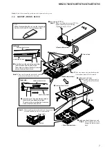
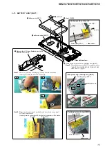
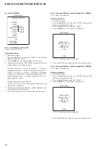
2-11. BATTERY ASSY (BAT1)
5
2
sheet (PWB)
3
sheet (D)
6
adhesive sheet (BATT)
7
battery assy (BAT1)
battery assy (BAT1)
4
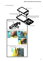
Remove two solders of wire of battery assy (BAT1).
Note 3:
When the battery assy (BAT1) is removed, refer to
“ABOUT THE HANDLING OF THE BATTERY
ASSY (BAT1)” (page 5).
wire of battery assy (BAT1)
MOTHER board
red
gap
black
:LUHSURFHVVLQJRIEDWWHU\DVV\%$7
OK
NG
1
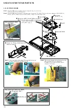
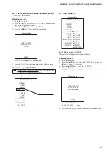
Remove the LCD assy flexible board in the
direction of arrow
A
.
3DVWLQJSRVLWLRQRIVKHH'
–
5HDUERWWRPYLHZ
–
–
5HDUYLHZ
–
A
two ditches
two ribs
Note 1:
There is a possibility of damaging LCD assy flexible board when
removing excluding the direction of arrow
A
.
Note 2:
Please match the position of two ditches and two ribs when you install
LCD assy flexible board.
If putting into the connector shift ditch and rib, connector will be broken.
OK
NG
NG
sheet (PWB)
MOTHER board
3DVWLQJSRVLWLRQRIVKHHW3:%
bottom side
sheet (D)
top side


