background image

NWZ-X1050/X1051/X1060/X1061

7

METHOD  OF  JUDGING  RIGHT  AND  WRONG  OF 


PARTS  RELATED  TO  SWITCH

In this set, only a part of parts that relate to the switch are supplied. 
Exchange the entire mounted board when parts that do not corre-
spond to it are defective.
The right and wrong of the switch can be judged by the following 
two methods.

1.  Judgment From The Test Mode

Judge the right and wrong of the switch referring to “4-4-2. Key 
check” (page 22).

2.  Judgment from the voltage measurement

Judge the right and wrong of the switch by the voltage measure-
ment with a test point.

2-1. [

u

]/[

>

]/[

.

] keys

Connection:

+

digital voltmeter

CL881 (KEY_AD0)

CL885 (GND)

When the voltage value is below, [

u

]/[

>

]/[

.

] keys are 

normal.
• [

u

] key is pressed 

: 0 to 0.25 V

• [

>

] key is pressed 

: 0.4 to 0.6 V

• [

.

] key is pressed 

: 0.76 to 0.95 V

2-2.  [VOL +]/[VOL –]/[HOME] keys
Connection:

+

digital voltmeter

CL882 (KEY_AD1)

CL885 (GND)

When the voltage value is below, [VOL +]/[VOL –]/[HOME] keys 
are normal.
• 

[VOL –] key is pressed  : 0 to 0.25 V

• 

[VOL +] key is pressed  : 0.4 to 0.6 V

• 

[HOME] key is pressed : 0.76 to 0.95 V

2-3.  HOLD switch (S881)
Connection:

+

digital voltmeter

S881 (HOLD SW pin 

2

)

CL885 (GND)

When the voltage value is below, HOLD switch (S881) is normal.
• 

HOLD switch is turned on  : 2.85 V

• 

HOLD switch is turned off : 0 V

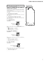
Connection location:

CL881

(KRY_AD0)

CL882

(KEY_AD1)

CL885
(GND)

S881

S881

(HOLD SW)

1

2

– MAIN Board (Side B) –

Note: 

Refer to page 27 for the schematic diagram. Refer to page 
28 for the printed wiring boards.

Summary of Contents for NWZ-X1050

Page 1: ...ain profile Bit rate Simple profile Max 1 700 kbps main profile Max 5 000 kbps Frame rate Max 30 fps Resolution Simple profile Max 480 270 main profile Max QVGA 320 240 Audio Formats Codec AAC LC for AVC MPEG 4 Channel number Max 2 channels Sampling frequency 1 24 32 44 1 48 kHz Bit rate Max 288 kbps channel WMA for Windows Media Video 9 Bit rate 32 to 192 kbps Supports variable bit rate VBR Sampl...

Page 2: ...tion in the United States States and or other countries x and are trademarks of Sony Corporation x Adobe and Adobe Reader are trademarks or registered trademarks of Adobe Systems Incorporated in the United States and or other countries x Manufactured under license from Dolby Laboratories Dolby and the double D symbol are trademarks of Dolby Laboratories x MPEG Layer 3 audio coding technology and p...

Page 3: ...unleaded solder but unleaded solder may also be added to ordinary solder CAUTION Danger of explosion if battery is incorrectly replaced Replace only with the same or equivalent type SECTION 1 SERVICING NOTES System Requirements x Computer IBM PC AT or compatible computer preinstalled with the following Windows operating systems Windows XP Home Edition Service Pack 2 or later Windows XP Professiona...

Page 4: ...ll be deleted Proceed appears 2 Select Yes All data will be deleted Proceed appears x To cancel the operation select No 3 Select Yes When initialization finishes Memory formatted appears x To cancel the operation select No 2 Reset all setting Reset All Settings You can reset the player to the default settings Resetting the player also deletes the wireless LAN encryption key but does not delete dat...

Page 5: ...e refer to the operation guide of this set for the confirm method of MAC address confirming Note The MAC address of this set was changed along with this repair Please set it again if you are using the MAC address filtering function of access point device of connection destination Please refer to the operation guide of this set for the confirm method of MAC address confirming Note The MAC address o...

Page 6: ...NWZ X1050 X1051 X1060 X1061 6 MEMO ...

Page 7: ...ltmeter CL881 KEY_AD0 CL885 GND When the voltage value is below u keys are normal u key is pressed 0 to 0 25 V key is pressed 0 4 to 0 6 V key is pressed 0 76 to 0 95 V 2 2 VOL VOL HOME keys Connection digital voltmeter CL882 KEY_AD1 CL885 GND When the voltage value is below VOL VOL HOME keys are normal VOL key is pressed 0 to 0 25 V VOL key is pressed 0 4 to 0 6 V HOME key is pressed 0 76 to 0 95...

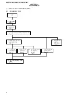
Page 8: ...LD ASSY Page 9 2 4 MAIN BOARD ASSY INCLUDING BATTERY ASSY Page 10 2 5 BATTERY ASSY BATT1 MAIN BOARD Page 10 2 6 5PIN HP JACK ASSY J001 CHASSIS SECTION Page 11 2 7 KEY FLEXIBLE PRINT BOARD FPC1 CHASSIS Page 12 2 11 TOUCH PANEL MODULE TPM1 FRAME Page 14 2 8 EL INDICATOR ELEMENT EL01 Page 12 2 10 BUTTON VOL KNOB NC Page 13 2 9 HOME KEY BOARD GUARD MULTI Page 13 ...

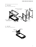
Page 9: ...3 HOLD ASSY Note This illustration sees the set from rear side 1 two screws M1 4 4 hold assy panel rear section 7 two adhesive sheet rear 8 panel rear 5 claw panel 6 plate rear 3 claw 2 Peel off panel rear section of the hold assy side in the adhesive sheet rear two places Note 2 Please work noting that the panel rear is damaged 1 screw M1 4 3 hold assy 2 screw B1 4 ...

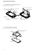
Page 10: ...sy in the direction of the arrow q MAIN board assy including battery assy 2 battery connector CN901 1 cushion B connector 5 5pin HP jack assy flexible board CN301 7 Move the MAIN board assy in the direction of the arrow 3 key flexible print board CN881 4 touch panel module flexible board CN882 9 EL indicator element flexible board CN801 1 Peel off the protection sheet battery in the direction of t...

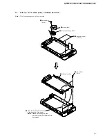
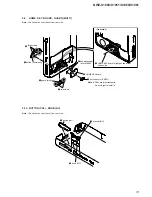
Page 11: ...ation sees the set from rear side 1 two screws M1 4 5 two screws M1 4 7 chassis section 2 holder jack 3 5pin HP jack assy J001 4 insulation sheet O FPC 6 Open the EL indicator element in the direction of the arrow Note 2 Please work noting that the EL indicator element flexible board is damaged ...

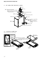
Page 12: ...hat the key flexible print board FPC1 is damaged 3 lid top 5 button top 9 spacer vol qf chassis 8 base top qs Peel off key flexible print board FPC1 of the chassis Note 1 Please work noting that the key flexible print board FPC1 is damaged 1 Remove the EL indicator element EL01 in the direction of the arrow Direction where EL indicator element is peeled off frame section rear side 2 EL indicator e...

Page 13: ...NC Note This illustration sees the set from rear side 4 HOME KEY board is lightiy pushed from button side 2 three claws 7 two claws 6 adhesive sheet home PWB 1 dot connector CN001 5 HOME KEY board 8 guard multi 3 button home assy Note 2 They are important parts Do not forget to install it front side 1 button vol 2 bracket NC 3 knob NC ...

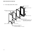
Page 14: ...ing that the touch panel module section is damaged of the frame 7 adhesive sheet window 3 adhesive sheet catch q frame 8 adhesive sheet lid 9 adhesive sheet lid B 5 cushion OLED Note 2 Adhesive sheet window cannot re used please replace to brand new part ones adhesive sheet window is removed Note 1 Please work noting that the touch panel module flexible board is damaged ...

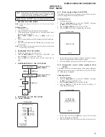
Page 15: ...k VCHK This mode is used in case power supply voltage in the state where all power supply lines are starting is checked Checking method 1 Enter the test mode 2 Press the key to select the POWER and press the u key to enter the minor item 3 Press the key to select the VCHK 4 Press the u key all power supply lines are started Screen display POWER VCHK START In this state the power supply voltage of ...

Page 16: ...ey is pressed the port setting for the charge is changed as shown in the table below Port control Display CHG_XCHGEN CHG_PEN1 CHG_PEN2 AC L H H USB500 L H H USB100 L H L 6 Press the HOME key return to minor item selection screen 4 1 5 Battery voltage detection check BATTCHK This mode is used in case battery voltage is checked Checking method 1 Enter the test mode 2 Press the key to select the POWE...

Page 17: ...finity Zero HPOUT VOL 30 START 5 Press the HOME key return to minor item selection screen 4 2 3 Frequency characteristic 1 check F1 20 Hz 0 dBs L ch R ch VOLUME 25 audio signal is outputted Checking method 1 Enter the test mode 2 Press the key to select the AUDIO and press the u key to enter the minor item 3 Press the key to select the F1 4 Press the u key 20 Hz 0 dBs L ch R ch VOLUME 25 audio sig...

Page 18: ...aximum output check MAXOUT 1 kHz 0 dBs L ch R ch VOLUME 30 Headphone output when AVLS operates 1 kHz 0 dBs L ch R ch VOLUME 14 audio signal is outputted Checking method 1 Enter the test mode 2 Press the key to select the AUDIO and press the u key to enter the minor item 3 Press the key to select the MAXOUT 4 Press the u key 1 kHz 0 dBs L ch R ch VOLUME 30 Headphone output when AVLS operates 1 kHz ...

Page 19: ...signal is outputted Screen display AUDIO SPKCHK 20 20kHz 0dBs L Rch HPOUT VOL 30 START 5 Press the HOME key return to minor item selection screen 4 2 11 User specification contents playback 1 USER1 User1 oma is reproduced Checking method 1 Enter the test mode 2 Press the key to select the AUDIO and press the u key to enter the minor item 3 Press the key to select the USER1 4 Press the u key User1 ...

Page 20: ... key is pressed the screen display changes in the following order All black default Color bar standard Color bar brightness minimum Color bar brightness maximum All red All green All blue All white diagonal gra dation red diagonal gradation green diagonal grada tion blue diagonal gradation white Maximum draw ing size confirmation Maximum drawing size confirmation All blue All sides are red is disp...

Page 21: ...3 Press the key to select the USER3 4 Press the u key User3 mp4 is reproduced Screen display VIDEO USER3 HPOUT VOL 15 XX XX START XX XX Repetition expert totaling time 5 Press the HOME key return to minor item selection screen 4 4 Other OTHER Screen display MPTAPP X XX XX POWER AUDIO VIDEO OTHER CLOCK CLESTE KEY DAC KEYNUM WIFI TOUCH FM FORMAT NC DEST SHUTDOWN SPSET EXITTEST FWVER NCAPCHK 4 4 1 Cl...

Page 22: ...n which the touch panel is pushed at that time is displayed Screen display OTHER TOUCH 0 60fps XX XX XX XX XX XX XX XX XX XX XX NO GESTURE 5 Press the HOME key return to minor item selection screen 4 4 5 Format FORMAT The user s area is formatted and ICV for the video and ICV for audio are initialized Note Not used for the servicing Format the set from Settings Common settings Format when it home ...

Page 23: ... return to minor item selection screen 4 5 CLESTE Screen display MPTAPP X XX XX POWER AUDIO VIDEO OTHER CLESTE WCABLE DAC WOCABLE WIFI FM NC SHUTDOWN EXITTEST 4 5 1 Clear stereo setting With cable WCABLE This mode is according to an original sound playback for adjust ment to right and left sound Note Not used for the servicing 4 5 2 Clear stereo setting No cable WOCABLE This mode is according to a...

Page 24: ...h XXXXMHz XXMbps 5 In this state each time the VOL VOL keys are pressed the transmission channel is changed 6 In this state each time the keys are pressed the transmission bit rate is changed 7 Press the HOME key return to minor item selection screen 4 7 3 Consecutive Wi Fi receptions RX Checking method 1 Enter the test mode 2 Press the key to select the WIFI and press the u key to enter the minor...

Page 25: ...ressed dis played page is changed 6 In this state each time the u key is pressed access point information is acquired again 7 Press the HOME key return to minor item selection screen 4 7 7 Wi Fi access point connection APCONN Checking method 1 Enter the test mode 2 Press the key to select the WIFI and press the u key to enter the minor item 3 Press the key to select the APCONN 4 Press the u key th...

Page 26: ...7 75 MHz 87 50 MHz 98 00 MHz 108 00 MHz 5 Press the HOME key return to minor item selection screen 4 9 NC Screen display MPTAPP X XX XX POWER AUDIO VIDEO OTHER CLESTE DAC WIFI FM NC GAIN L SHUTDOWN GAIN R EXITTEST 4 9 1 Microphone gain L ch adjustment GAIN L Microphone gain L ch is adjusted Note Not used for the servicing 4 9 2 Microphone gain R ch adjustment GAIN R Microphone gain R ch is adjuste...

Page 27: ... However the patterns of intermediate layers have not been in cluded in diagrams Lead layouts surface CSP Chip Size Package Lead layout of conventional IC Note 2 When the MAIN board is replaced there are some notes Refer to NOTE THE MAIN BOARD REPLACING page 4 in servicing notes for notes Note 1 In this set only a part of parts that relate to the switch are supplied Therefore the schematic diagram...

Page 28: ...21 C22 C23 C24 C25 C26 D1 D2 D3 D4 D5 D6 D7 D8 D9 D10 D11 D12 D13 D14 D15 D16 D17 D18 D19 D20 D21 D22 D23 D24 D25 D26 E1 E2 E3 E4 E5 E6 E7 E8 E9 E10 E11 E12 E13 E14 E15 E16 E17 E18 E19 E20 E21 E22 E23 E24 E25 E26 F1 F2 F3 F4 F5 F22 F23 F24 F25 F26 G1 G2 G3 G4 G5 G22 G23 G24 G25 G26 H1 H2 H3 H4 H5 H8 H9 H10 H11 H12 H13 H14 H15 H16 H17 H18 H19 H22 H23 H24 H25 H26 J1 J2 J3 J4 J5 J8 J9 J10 J11 J12 J13...

Page 29: ...mean standardized parts so they may have some difference from the original one Items marked are not stocked since they are seldom required for routine ser vice Some delay should be anticipated when ordering these items The mechanical parts with no reference number in the exploded views are not sup plied Color Indication of Appearance Parts Ex ample KNOB BALANCE WHITE RED Parts Color Cabinet s Colo...

Page 30: ...RAD COMPLETE 32G for SERVICE NWZ X1060 TW 54 9 885 133 47 MAIN BORAD COMPLETE 32G for SERVICE NWZ X1060 E AUS JE 54 9 885 133 48 MAIN BORAD COMPLETE 32G for SERVICE NWZ X1060 CH 54 9 885 133 49 MAIN BORAD COMPLETE 32G for SERVICE NWZ X1060 MX 54 9 885 133 50 MAIN BORAD COMPLETE 32G for SERVICE NWZ X1060 CND 54 9 885 133 51 MAIN BORAD COMPLETE 32G for SERVICE NWZ X1060 AEP UK 54 9 885 133 53 MAIN B...

Page 31: ... 01 SPACER VOL 122 4 112 870 01 BASE TOP 123 4 112 887 01 COVER RESET CN01 1 822 382 11 CONNECTOR DOT EL01 1 802 813 11 ELEMENT EL INDICATOR FPC1 1 877 868 11 KEY FLEXIBLE PRINT BOARD TPM1 1 480 788 11 TOUCH PANEL MODULE Ref No Part No Description Remark Ref No Part No Description Remark 101 102 103 104 105 106 107 109 110 111 112 113 116 117 118 119 120 121 122 123 B C D E A TPM1 CN01 EL01 FPC1 N...

Page 32: ...1 METAL CHIP 10K 0 5 1 16W R889 1 208 911 11 METAL CHIP 10K 0 5 1 16W R890 1 208 911 11 METAL CHIP 10K 0 5 1 16W R891 1 208 911 11 METAL CHIP 10K 0 5 1 16W R892 1 218 985 11 METAL CHIP 470K 5 1 16W R893 1 240 726 91 METAL CHIP 470K 5 1 20W R895 1 240 760 91 METAL CHIP 100 0 5 1 20W R896 1 240 760 91 METAL CHIP 100 0 5 1 20W R897 1 218 990 81 SHORT CHIP 0 SWITCH S881 1 786 455 32 SWITCH PUSH 1 KEY ...

Page 33: ...QSG INSTRUCTION Quick Start Guide TRADITIONAL CHINESE E AUS TW JE 4 137 988 91 MANUAL QSG INSTRUCTION Quick Start Guide KOREAN E AUS JE 4 137 989 11 MANUAL QSG INSTRUCTION Quick Start Guide UKRAINIAN EE 4 137 989 31 MANUAL QSG INSTRUCTION Quick Start Guide ARABIC E AUS JE X 2349 337 1 SOFT APPLICATION ASSY CD ROM Windows Media Player 11 Content Transfer Operation Guide PDF file NWZ X1051 X1061 X 2...

Page 34: ...1 REVISION HISTORY Checking the version allows you to jump to the revised page Also clicking the version at the top of the revised page allows you to jump to the next revised page Ver Date Description of Revision 1 0 2009 05 New ...

Reviews: