


Connecting peripheral devices
PC Cards
Sony
Not
e
book
Com
p
ut
er
Us
er
Gui
d
e
53
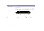
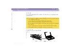
PC Cards
Your computer includes two PC card slots. PC cards allow you to connect portable
external devices.
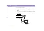
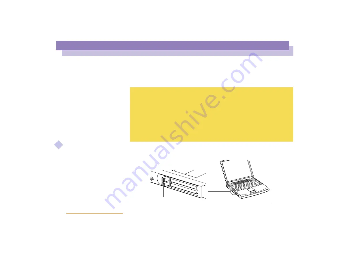
To insert a PC card
Use the lower slot for PC type III cards.
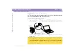
The PC card slots can accommodate (at the same time) two Type I, two Type II, or one Type III PC card. These
slots are compatible with Card Bus port.
Some PC cards may require that you disable idle devices when using the PC card.
Be sure to use the most recent software driver provided by the PC card manufacturer.
If an “!” mark appears on the Device Manager tab in the System Properties dialog, remove the software driver
and then reinstall it.
You may not be able to use some PC cards or some functions within the PC card with this computer.
You do not need to shut down the computer before inserting or removing a PC card.
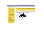
RELEASE button


