background image

— 2 —

Information in this document is subject to change without notice.

Sony and VAIO are trademarks of Sony. Intel logo and Intel Inside

logo are registered trademarks of Intel Corporation. Pentium MMX

is a trademark of Intel Corporation. Microsoft, MS-DOS, Windows,

the Windows 95 and Windows 98 logo are trademarks of Microsoft

Corporation.

All other trademarks are trademarks or registered trademarks of

their respective owners. Other trademarks and trade names may be

used in this document to refer to the entitles claiming the marks and

names or their produces. Sony Corporation disclaims any proprietary

interest in trademarks and trade names other than its own.

Service and Inspection Precautions

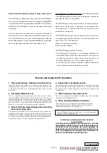
1. Obey precautionary markings and instructions

Labels and stamps on the cabinet, chassis, and components identify areas
requiring special precautions.  Be sure to observe these precautions, as well
as all precautions listed in the operating manual and other associated
documents.

2. Use designated parts only

The set’s components possess important safety characteristics, such as
noncombustibility and the ability to tolerate large voltages.  Be sure that
replacement parts possess the same safety characteristics as the originals.
Also remember that the 

0

 mark, which appears in circuit diagrams and

parts lists, denotes components that have particularly important safety
functions; be extra sure to use only the designated components.

3. Always follow the original design when mounting

parts and routing wires

The original layout includes various safety features, such as inclusion of
insulating materials (tubes and tape) and the mounting of parts above the
printer board.  In addition, internal wiring has been routed and clamped so
as to keep it away from hot or high-voltage parts.  When mounting parts or
routing wires, therefore, be sure to duplicate the original layout.

4. Inspect after completing service

After servicing, inspect to make sure that all screws, components, and wiring
have been returned to their original condition.  Also check the area around
the repair location to ensure that repair work has caused no damage, and
confirm safety.

5. When replacing chip components...

Never reuse components.  Also remember that the negative side of tantalum
capacitors is easily damaged by heat.

6.  When handling flexible print boards...

• The temperature of the soldering-iron tip should be about 270C.
• Do not apply the tip more than three times to the same pattern.
• Handle patterns with care; never apply force.

Caution: Remember that hard disk drives are easily damaged by
vibration.  Always handle with care.

Caution Markings for Lithium/Ion Battery - The following or similar

texts shall be provided on battery pack of equipment or in both the

operating and the service instructions.

CAUTION: Danger of explosion if battery is incorrectly replaced.

Replace only with the same or equivalent type recommended by

the manufacturer.  Discard used batteries according to the

manufacturer’s instructions.

CAUTION: The battery pack used in this device may present a fire

or chemical burn hazard if mistreated.  Do not disassemble, heat

above 100

°

C (212

°

F) or incinerate.

Dispose of used battery promptly.

Keep away from children.

CAUTION: Changing the back up battery.

• Overcharging, short circuiting, reverse charging, multilation or

incineration of the cells must be avoided to prevent one or more of

the following occurrences; release of toxic materials, release of

hydrogen and/or oxygen gas, rise in surface temperature.

• If a cell has leaked or vented, it should be replaced immediately

while avoiding to touch it without any protection.

ATTENTION AU COMPOSANT AYANT RAPPORT

À LA SÉCURITÉ!

LES COMPOSANTS IDENTIFÉS PAR UNE MARQUE 

0

 SUR LES

DIAGRAMMES SCHÉMATIQUES ET LA LISTE DES PIÈCES SONT
CRITIQUES POUR LA SÉCURITÉ DE FONCTIONNEMENT. NE
REMPLACER CES COMPOSANTS QUE PAR DES PIÈSES SONY
DONT LES NUMÉROS SONT DONNÉS DANS CE MANUEL OU
DANS LES SUPPÉMENTS PUBLIÉS PAR SONY.

Confidential

PCG-

GRX510/GRX510K/GRX510P/

GRX550/GRX550K/

PCG-GRX550P/GRX570/GRX570K/GRX570P/GRX590/

PCG-GRX590K/GRX590P (AM)

Summary of Contents for PCG-GRX550 VAIO User Guide (primary manual)

Page 1: ...K PCG GRX590 PCG GRX570P PCG GRX570K PCG GRX570 PCG GRX550P PCG GRX550K PCG GRX550 PCG GRX510P PCG GRX510K PCG GRX510 Design and specifications are subject to change without notice PCG GRX510 GRX510K GRX510P GRX550 GRX550K GRX550P PCG GRX570 GRX570K GRX570P GRX590 GRX590K RX590P S400 Ver 2 2002D Revision History Illust PCG GRX590P ...

Page 2: ... make sure that all screws components and wiring have been returned to their original condition Also check the area around the repair location to ensure that repair work has caused no damage and confirm safety 5 When replacing chip components Never reuse components Also remember that the negative side of tantalum capacitors is easily damaged by heat 6 When handling flexible print boards The temper...

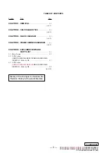
Page 3: ... 5 1 5 1 Main Section 5 3 5 2 LCD Section GRX570 GRX570K GRX570P GRX590 GRX590K GRX590P Made by HI 5 7 5 3 LCD Section GRX510 GRX510K GRX510P GRX550 GRX550K GRX550P Made by HI 5 9 to 5 10 Section Title Page Confidential History of the changes is shown as the Revision History at the end of this data PCG GRX510 GRX510K GRX510P GRX550 GRX550K PCG GRX550P GRX570 GRX570K GRX570P GRX590 PCG GRX590K GRX5...

Page 4: ...RX510 GRX510K GRX510P GRX550 GRX550K PCG GRX550P GRX570 GRX570K GRX570P GRX590 PCG GRX590K GRX590P AM CHAPTER 1 REMOVAL END ATTENTION Please confirm disassembly method by Repair Manual which has been informed you separately ...

Page 5: ...X510P GRX550 GRX550K PCG GRX550P GRX570 GRX570K GRX570P GRX590 PCG GRX590K GRX590P AM CHAPTER 2 SELF DIAGNOSTICS Please confirm Self Diagnostics method which will be informed you with distribution of Self Diagnostics software ATTENTION END ...

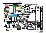
Page 6: ...EEPROM For VID EEPROM For i LINK MDC Modem Daughter Card Module CPU Local Bus EEPROM For Password USB Left CONN USB Rear CONN i LINK Dock VGA DB 15 Dock VGA DB 15 Serial Parallele RJ 45 RJ45 VGA DB 15 Video Out USB CONN USB CONN LineOut Port0 5 Optical Drive Primary Secondary IDE ATA100 AMP etc L in e O u t RJ 45 RJ 45 Parallele PS 2 CLKGEN IMI 9870GTD Port Repricator Parallele Parallele i LINK0 P...

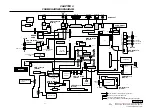
Page 7: ... A SWX 90 Board Side A IFX 193 Board Side A CNX 158 Board Side A CNX 159 Board Side A CNX 157 Board Side A CN7502 59 60 1 2 1 1 4 12 1 12 1 12 21 22 1 2 CN3102 CN1601 1 1 2 2 29 30 MODEM CARD J1 1 2 29 30 CN1301 CN851 CN855 CN1111 CN1501 CN3501 CN2005 CN2007 CN101 2 1 NICKEL HYDROGEN BATTERY CN3101 CN852 2 28 27 1 CN3004 120 2 1 119 CN1401 11 1 2 12 CN1124 11 1 2 1 2 12 1 12 1 1 20 12 CN2001 CN500...

Page 8: ... ordering these items When two or more parts are shown in parallel use the part described first as the main part The indication CH is used for identification of part type Regarding the boards of this model the discrete parts on the boards cannot be replaced However Some connectors can be replaced The components identified by mark 0 or dotted line with mark 0 are critical for safety Replace only wi...

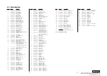
Page 9: ... 660 887 01 DISPLAY BASE 73 1 477 285 21 KEYBOARD UNIT U 74 X 4624 605 1 ASSY HOOD KEYBOARD 75 1 825 081 11 SPEAKER 2 8CM BOX WITH 76 1 823 719 11 CABLE FLEXIBLE FLAT 77 A 8067 178 A COMPLETE PWB IFX 193 78 1 823 720 11 CABLE FLEXIBLE FLAT 79 A 8067 173 A COMPLETE PWB SWX 90 80 A 8059 666 A GRX570 GRX570K GRX570P GRX590 GRX590K GRX590P ASSY HDD 40GB T 20 F S 80 A 8059 344 A GRX510 GRX510K GRX510P ...

Page 10: ...31 32 33 34 35 36 133 127 37 125 38 39 40 41 B1 B2 B8 B8 B8 B8 B8 B7 B7 B16 B1 B1 B2 B2 B2 B2 B15 B2 B2 B2 B2 B2 B2 B6 B2 B2 B2 B2 B17 B17 B17 B17 B6 B2 B2 B2 B16 112 111 110 B16 116 B2 B1 B15 B2 B15 42 43 44 98 85 45 46 47 49 92 93 117 50 51 119 52 53 55 134 56 57 58 59 60 61 62 88 88 87 63 64 65 135 66 68 69 70 94 71 72 73 74 120 75 126 76 77 78 79 80 81 82 83 84 129 101 101 67 130 121 131 122 1...

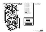
Page 11: ...CD SCREW COVER S 203 4 660 897 01 COVER HINGE 204 4 660 850 01 LCD SCREW COVER T 205 X 4624 525 1 ASSY BEZEL 206 4 660 846 01 LATCH RUBBER 207 A 8059 922 A ASSY LCD 16U HI S 208 4 660 839 02 BRACKET LCD L 209 4 660 840 02 BRACKET LCD R 210 1 961 573 11 HARNESS LCD 211 4 660 844 01 LATCH HOLDER LCD 212 4 660 828 01 LATCH GUIDE 213 4 660 907 01 LATCH_BOTTON 214 4 660 843 02 LATCH LEVER 215 1 477 101...

Page 12: ...COORS 4 662 303 01 SPECIFICATION SHEET COORS LOOK AT EXPLODED VIES OF THE PARTS 805 A 8023 271 A WIRELESS LAN PC CARD ASSY 806 X 4624 277 1 CASE ASSY PC CARD 801 AC Adaptor 1 802 Battery Pack 1 803 Power Cord 1 804 Weight Saver 1 805 Wireless LAN PC Card 1 806 Wireless LAN PC Card Case 1 END 301 4 660 897 01 COVER HINGE 302 X 4624 586 1 ASSY BEZEL DISPLAY 15 303 4 660 919 01 COVER SCREW LOWER 15 3...

Page 13: ...r reprinted in whole or in part without prior written authorization of Sony Corporation English 2002C1600 1 2002 Sony Corporation Published by Sony EMCS VAIO GSC SNT List of PCG GRX Series As of April 2002 Model Name PCG GRX550 PCG GRX550K PCG GRX550P PCG GRX570 PCG GRX570K PCG GRX570P PCG GRX590 PCG GRX590K PCG GRX590P PCG GRX510 PCG GRX510K PCG GRX510P Service Manual Part No 9 874 524 02 Additio...

Page 14: ...1 Ver 1 2002 03 25 First Edition 02 Ver 2 2002 04 23 Front Page Model Line Up Page 5 3 Page 5 4 Page 5 9 Back Cover N2002_047K Remarks Confidential PCG GRX510 GRX510K GRX510P GRX550 GRX550K GRX550P PCG GRX570 GRX570K GRX570P GRX590 GRX590K GRX590P AM ...

Reviews: