3-13
PCS-1500/1500P
64Mbit SDRAM(IC101,102)
(1Mx16bitx4bank x 2)
CKIO
CLK
CKE
\CS
\RAS
\CAS
\WE
A
0
-A
11
A
11
, A
12
LDQM
DQ
0
-DQ
31
32Mbit Flash RAM(IC103,104)
(2Mx16bit x 2)
MBM29DL324B-90PFTN
RY/BY
\CE
A
0
-A
19
DQ
0
-DQ
15
BYTE
\WE
\OE
RESET
CKE
\CS3
\RAS
\CAS
RD/WR
A
0
-A
25
D
0
-D
31
UDQM
WE2/DQMUL/ICIORD
WE1/DQMLU
WE0/DQMLL
WE3/DQMUU/ICIOWR
\CS0
\RD
CPU(IC100)
HD6417708S
30MHz
A
2
-A
13
A
22
,A
23
IOCS16
D
0
-D
15
A
0
-A
24
CE1
OE
WE/PGM
CD1&CD2,
Over Current of Power
RDY/BSY or IREQ,
WP or IOCS16
RFU/INPACK
BVD2 or SPKR,
BVD1 or STSCHG
CE2
IORD
IOWR
WAIT,RDY/BSY or IREQ
A
25
,REQ/REG,RESET
Buffer(IC131-133)
LVC244 or LCX244
G
Transceiver(IC130)
LVC245 or LCX245
CS6/CE1B
MD4/CE2B
A
2
-A
22
D
0
-D
15
D
16
-D
31
WAIT,IRL3-0
G
DIR
G
3
from I/O Port
from Bus Controller
Buffer(IC134)
LVC244 or LCX244
RY/BY
\CE
A
0
-A
20
DQ
0
-DQ
15
\BYTE
\WE
\OE
\RESET
\POR
from PCMCIA
Power Controller
3
7
MD3
MD5
CLK
CKE
\CS
\RAS
\CAS
\WE
A
0
-A
11
A
12
, A
13
LDQM
DQ
0
-DQ
15
UDQM
D
16
-D
31
D
0
-D
15
Supply Voltage Supervisor(IC115)
TLC7733
from IC115
Delay
\RESET
\POR
to Flash Memory & Bus Controller
\Reset CPU
to IC200
from Bus Controller
2
2
to Bus Controller
from
Bus Controller
Buffer(IC133)
LVC244 or LCX244
EXTAL
7.5MHz
from X100
+3.3V
PCMCIA Interface
SENSE
\RESET
MD2/RXD
MD1/TXD
from IC200
to IC200
Vcc=3.3V-2
Vcc=3.3V
Vcc=3.3V
Vcc=3.3V
Vcc=3.3V
16
from/to
DIAG PORT
26
A
0
-A
24
D
0
-D
15
D
8
-D
15
25
+12V
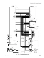
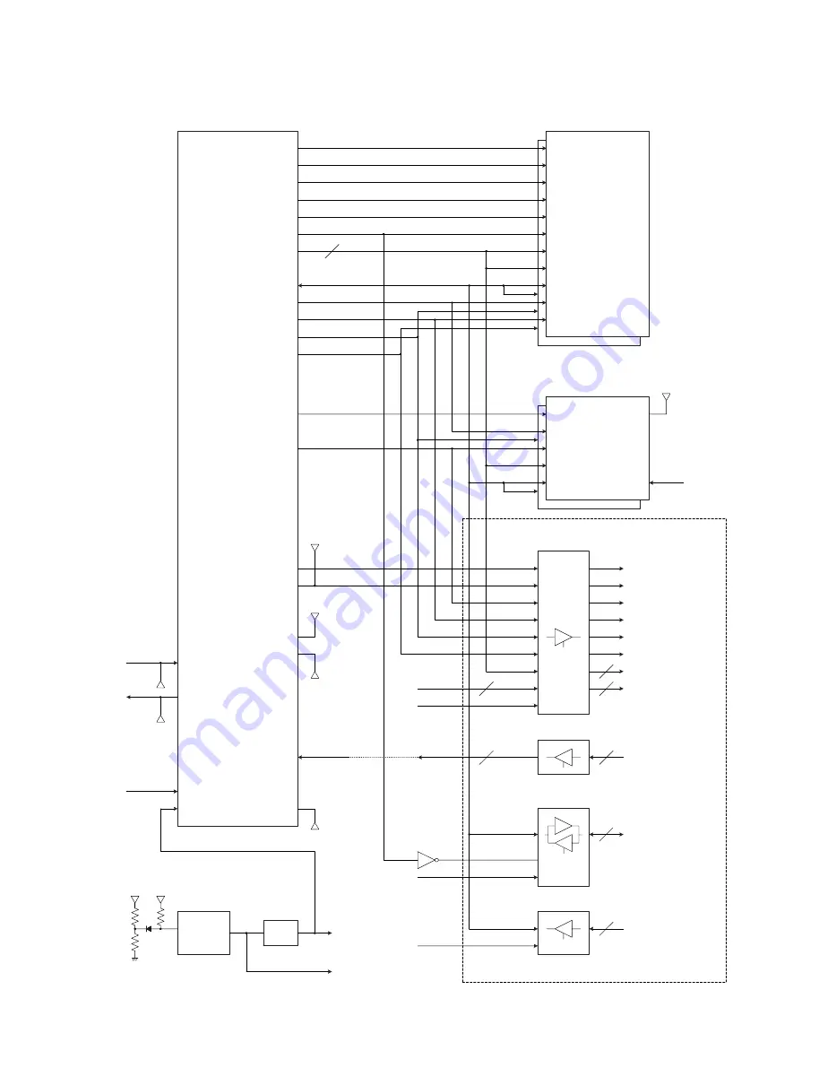
Fig. 3-6 Memory and PCMCIA I/F of CPU Block
3-2. Circuit Description of the Respective Boards
Summary of Contents for PCS-1500
Page 8: ......
Page 75: ...1 67 PCS 1500 1500P Sony Corporation Printed in Japan ...
Page 76: ......
Page 130: ......
Page 198: ......


