


– 3 –
PCV-L400/L600
TABLE OF CONTENTS
1.
OPERATION
2.
DISASSEMBLY
2-1. Flow Chart ........................................................................ 2-1
2-2. Memory Card ................................................................... 2-2
2-3. Top Cover ......................................................................... 2-2
2-4. HDD, Drive Holder .......................................................... 2-3
2-5. FDD, CD-ROM ................................................................ 2-3
2-6. Modem Card ..................................................................... 2-4
2-7. Riser Support, Riser Card ................................................ 2-4
2-8. Memory (DIMM) ............................................................. 2-5
Memory (DIMM) Installation .......................................... 2-5
2-9. CPU and Heat Sink .......................................................... 2-6
Heat Sink Installation ....................................................... 2-6
2-10. SWX-26, LEX-14 Board ................................................. 2-7
2-11. Power Supply ................................................................... 2-7
2-12. Drive Support ................................................................... 2-8
2-13. Main Board ....................................................................... 2-8
2-14. LCD Ass’y ........................................................................ 2-9
2-15. Front Cover Ass’y .......................................................... 2-10
2-16. LCD Panel ...................................................................... 2-10
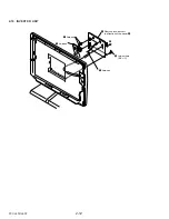
2-17. Inverter Unit ................................................................... 2-11
2-18. Main Electric Pats Arrangement .................................... 2-12
Main Section .................................................................. 2-12
Display Section .............................................................. 2-12
3.
MOTHERBOARD DESCRIPTION
...................... 3-1
4.
SERVICE INFORMATION
4-1. Jumper Setting on Hard Disk Drive ................................ 4-1
4-2. Jumper Setting of Main Board ......................................... 4-2
5.
BLOCK DIAGRAM
................................................... 5-1
6.
FRAME HARNESS
6-1. Connector List .................................................................. 6-1
6-2. Frame Harness Diagram .................................................. 6-7
7.
REPAIR PARTS LIST
7-1. Exploded views and Parts List (Main Section) ............... 7-1
7-2. Exploded views and Parts List (Display Section) ........... 7-3
7-3. Accessories and Parts List ............................................... 7-5
7-4. BarCord Label .................................................................. 7-6
Summary of Contents for PCV-L400 - Vaio Slimtop Computer
Page 1: ...SERVICE MANUAL PCV L400 L600 US Model Specifications PERSONAL COMPUTER VAIO 9 928 306 11 ...
Page 2: ...PCV L400 L600 US 9 928 306 11 99C204 1 ...
Page 3: ... 2 PCV L400 L600 ...
Page 5: ...1 1 PCV L400 L600 SECTION 1 OPERATION Reproduced from User Guide 3 866 380 01 ...
Page 19: ...3 1 PCV L400 L600 SECTION 3 MOTHERBOARD DESCRIPTION ...
Page 20: ...3 2 PCV L400 L600 ...
Page 21: ...3 3 PCV L400 L600 3 3 END ...
Page 25: ...6 1 PCV L400 L600 SECTION 6 FRAME HARNESS 6 1 Connector List ...
Page 26: ...6 2 PCV L400 L600 ...
Page 27: ...6 3 PCV L400 L600 ...
Page 28: ...6 4 PCV L400 L600 ...
Page 29: ...6 5 PCV L400 L600 ...
Page 30: ...6 6 PCV L400 L600 ...


