7
(GB)
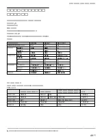
Location and Function of Parts and Controls
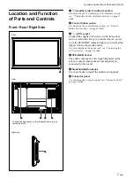
Location and Function
of Parts and Controls
Front / Rear / Right Side
Front
Right side
Rear
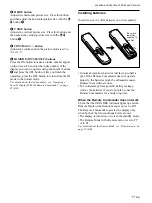
1
1
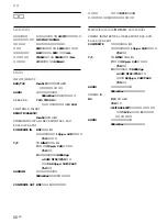
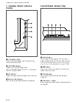
(standby) switch / indicator section
For details on the
1
(standby) switch / indicator section,
see “
1
(standby) Switch / Indicator Section” on page 8
(GB).
2
Control button section
For details on the control button section, see “Control
Button Section (Top)” on page 8 (GB).
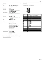
3
-
AC IN socket
Connect the supplied AC power cord to this socket
and to a wall outlet. Once you connect the AC power
cord, the STANDBY indicator lights up in red and the
display turns to the standby mode.
For more details on the power cord, see “Connecting the
AC Power Cord” on page 13 (GB).
4
SPEAKER Socket
The audio component of the signal displayed on the
screen is output when speakers (not supplied) are
connected to this socket.
5
Stand installation hooks
Use these hooks to install the stand (not supplied).
6
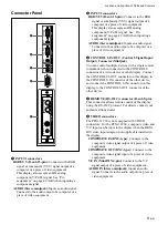
Connector panel
For details on the connector panel, see “Connector Panel”
on page 9 (GB).
O
N
S
TA
N
D
B
Y
1
3
2
5
4
6
INPUT 1
RGB /
YUV
A
UDIO
INPUT 2
CONTR
O
L S
REMO
T
E
RGB /
YUV
A
UDIO
IN
OUT
COMPOSITE
IN
OUT
Y/C IN
A
UDIO IN
VIDEO
The shaded areas shown in the illustration above are all
ventilation holes.
Summary of Contents for PFM-32C1
Page 53: ...53 JP ...
Page 199: ......
Page 297: ......
Page 298: ...2 CS 警告 为避免引发意外的火灾或遭受雷击的危险 请勿将 本机置于雨点所及或者潮湿的地方 输出插座应安装于装置附近使用方便的地方 ...
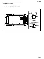
Page 311: ...15 CS 连接 使用电缆夹 可用附带的电缆夹 5 个 有效地捆扎扬声器电 缆 请按下图所示的方法安装电缆夹 1 2 后视图 取下去皮 纸遮盖物 请按图所示 的方法粘贴 电缆夹 ...
Page 346: ......
Page 347: ......
Page 348: ...Sony Corporation Printed in Japan ...

