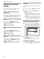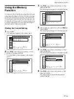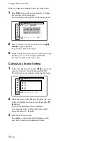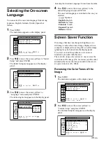
24
(GB)
Watching the Picture
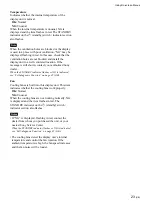
INPUT2 (RGB): Selects the audio and video
signal input from the INPUT2 connectors
when the input signal is an RGB signal.
INPUT2 (COMPONENT): Selects the audio and
video signal input from the INPUT2
connectors when the input signal is a
component signal.
VIDEO (COMPOSITE): Selects the audio and
video signal input from the COMPOSITE
IN connector and AUDIO IN jack among
the VIDEO connectors.
VIDEO (Y/C): Selects the audio and video signal
input from the Y/C IN connector and
AUDIO IN jack among the VIDEO
connectors.
The selected input signal appears on the display
panel.
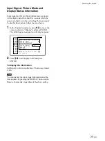
I N P U T 1 ( R G B )
1 0 2 4
7 6 8 / 6 0
S t a n d a r d
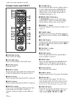
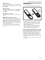
You can switch the input signal using the Remote
Commander supplied with your display panel.
Note
We recommend input source video equipment
equipped with a TBC (time base corrector). If the
display receives a signal without TBC, the picture
may disappear due to disturbance of the sync signal.
Watching the Picture
Before you start
• Turn on the display.
• Turn on the connected equipment and play a video
source.
• To display the input signal information and Picture
Mode on the screen when turning on the power or
switching the input signal, set “Display” in the
Custom Setup menu to On.
• To select the on-screen language used in the menu,
see page 39 (GB).
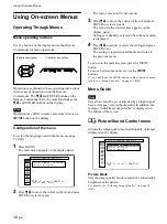
Switching the Input Signal
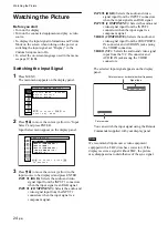
1
Press MENU.
The main menu appears on the display panel.
,
t o
s e l e c t ,
,
t o
ENTER
P i c t u r e / S o u n d
C o n t r o l
P i c t u r e
M o d e
: S t a n d a r d
A d j u s t
P i c t u r e
A d j u s t
S o u n d
e n t e r
a d j .
m e n u
2
Press
M
/
m
to move the cursor (yellow) to “Input
Select” and press ENTER.
Input Select menu appear on the display panel.
I n p u t
S e l e c t
I N P U T 1 ( R G B )
I N P U T 1 ( C O M P O N E N T )
I N P U T 2 ( R G B )
I N P U T 2 ( C O M P O N E N T )
V I D E O ( C O M P O S I T E )
V I D E O ( Y / C )
,
t o
s e l e c t ,
p r e s s
ENTER
t o
e x e c u t e
3
Press
M
/
m
to move the cursor (yellow) to the
input source to be displayed and press ENTER.
INPUT1 (RGB): Selects the audio and video
signal input from the INPUT1 connectors
when the input signal is an RGB signal.
INPUT1 (COMPONENT): Selects the audio and
video signal input from the INPUT1
connectors when the input signal is a
component signal.
Color system or horizontal/vertical frequency
Signal type
Picture mode
Summary of Contents for PFM-32C1
Page 53: ...53 JP ...
Page 199: ......
Page 297: ......
Page 298: ...2 CS 警告 为避免引发意外的火灾或遭受雷击的危险 请勿将 本机置于雨点所及或者潮湿的地方 输出插座应安装于装置附近使用方便的地方 ...
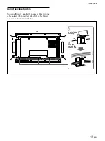
Page 311: ...15 CS 连接 使用电缆夹 可用附带的电缆夹 5 个 有效地捆扎扬声器电 缆 请按下图所示的方法安装电缆夹 1 2 后视图 取下去皮 纸遮盖物 请按图所示 的方法粘贴 电缆夹 ...
Page 346: ......
Page 347: ......
Page 348: ...Sony Corporation Printed in Japan ...

