4
(E)
PL101
2-2. Preparation
.
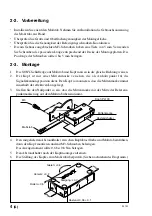
First, install the scale. For the installation procedure, refer to the instruction manual for
the scale.
.
Check the range and surface accuracy of the installation surface.
.
Check the accuracy of the mounting screw coordinates.
.
The M3 tap screws mounted on the case have a depth of 5 mm. Obtain screws with a
suitable length according to the thickness of the mounting brackets. The fitting length of
the screws should be 4 to 5 mm.
2-3. Installation
1.
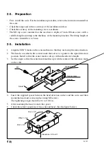
Align the SONY marks on the scale and head so that they are facing the same direction.
2.
The head is inscribed with a center mark that serves as a guide to the signal detection
position. Install so that the center mark is always within the effective length.
3.
Set the origin so that the center mark matches up with the center of the reference mark
on the scale.
4.
Insert the supplied spacer between the head detection surface and the scale, and then
mount the head and secure in place using M3 screws.
The tightening torque should be 0.6 to 0.8 N
⋅
m.
5.
After mounting the head, remove the spacer.
6.
Check the relative positions of the scale and head. (See the figure below.)
Spacer
M3
Scale
Head (PL101)
Center mark
Clearance: 0.35
±
0.1
Yaw:
±
0.2
d
Offset:
±
0.2
Roll:
±
0.2
d
Pitch:
±
0.1
d
Summary of Contents for PL101 Series
Page 6: ...PL101 ii J ...
Page 16: ...PL101 ii E ...
Page 26: ...PL101 ii G ...
Page 33: ...PL101 ...


