– 34 –
4-1.
IC PIN FUNCTION DESCRIPTION
SECTION 4
DIAGRAMS
•
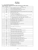
RG-46P BOARD IC401 CXA1854AR (LCD VIDEO SIGNAL PROCESSOR, LCD TIMING CONTROL)
Pin No.
Pin Name
I/O
Function
1
SYNCIN
I
Video signal (brightness signal) input to the sync separation circuit
2
YIN
I
Video signal (brightness signal) input terminal
3
AGCADJ
I
AGC level setting signal input from the D/A converter (IC402)
4
AGCTC
O
Connected to the time constant circuit for AGC
5
PICT
I
Brightness signal frequency characteristics setting signal input from the D/A converter (IC402)
6
GND1
—
Ground terminal (analog system)
7
MODE1
I
8
MODE2
I
For selecting composite/brightness color difference/brightness-chroma signal
“H”: composite signal input, “M” (middle setting): brightness color difference signal input,
“L”: brightness-chroma signal input Not used (open)
9
EXT-R
I
External digital input R signal Not used (fixed at “L”)
10
EXT-G
I
External digital input G signal Not used (fixed at “L”)
11
EXT-B
I
External digital input B signal Not used (fixed at “L”)
12
RPD
O
PLL phase comparator output terminal
13
VSS
—
Ground terminal (digital system)
14
CKI
I
Master clock signal input from the D/A converter (IC402)
15
CKO
O
Master clock signal output terminal
16
TEST2
I
17
TEST1
I
Input terminal for the test (Normally: open)
18
TEST0
I
19
SLCK
I
Fixed at “L” in this set
20
VST2
O
Vertical start pulse output to the left LCD unit
Output of vertical scanning start pulse signal added to gate driver
21
VST1
O
Vertical start pulse output to the right LCD unit
Output of vertical scanning start pulse signal added to gate driver
22
VCK2
O
23
VCK1
O
24
EN
O
Enable pulse signal output to the left and right LCD units
25
CLR
O
Clear pulse signal output to the left and right LCD units
26
TEST4
O
Output terminal for the test (Normally: open)
27
HST1
O
Horizontal start pulse output to the left and right LCD units
Output of horizontal sampling start pulse signal added to source driver
28
HCK2
O
29
HCK1
O
30
HD
O
Horizontal drive pulse output terminal Not used (open)
31
VD
O
Vertical drive pulse output terminal
32
TEST5
I
Input terminal for the test (Normally: open)
33
VDD
—
Power supply terminal (+5V) (digital system)
34
RGT
I
For selecting scan mode
“H”: normal scan mode, “L”: reverse scan mode (fixed at “L” in this set)
Vertical shift clock output to the left and right LCD units
Output of vertical shift clock signal added to gate driver
Horizontal shift clock output to the left and right LCD units
Output of horizontal shift clock signal added to source driver
For selecting video mode (NTSC/PAL)
“H”: NTSC, “L” or “M” (middle setting) : PAL
At “L”, SPAL (chroma demodulation is executed internally), At “M” (middle setting), DPAL
(external delay line is used for demodulation) (fixed at “H” in this set)
Summary of Contents for PLM-A55E
Page 1: ...SERVICE MANUAL GLASSTRON AEP Model UK Model SPECIFICATIONS PLM A55E 9 928 101 31 ...
Page 3: ... 3 SECTION 1 GENERAL This section is extracted from instruction manual ...
Page 4: ... 4 ...
Page 5: ... 5 ...
Page 6: ... 6 ...
Page 7: ... 7 ...
Page 8: ... 8 ...
Page 9: ... 9 ...
Page 10: ... 10 ...
Page 11: ... 11 ...
Page 12: ... 12 ...
Page 13: ... 13 ...
Page 14: ... 14 ...


