4.
Remove the outside panel assembly. (Refer to
“2-5-1. Outside Panel Assembly”
.)
5.
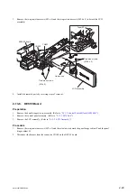
Remove the top panel assembly. (Refer to
6.
Remove the front panel assembly. (Refer to
Procedure
1.
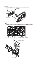
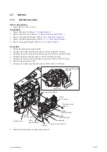
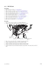
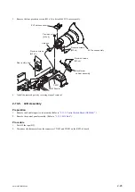
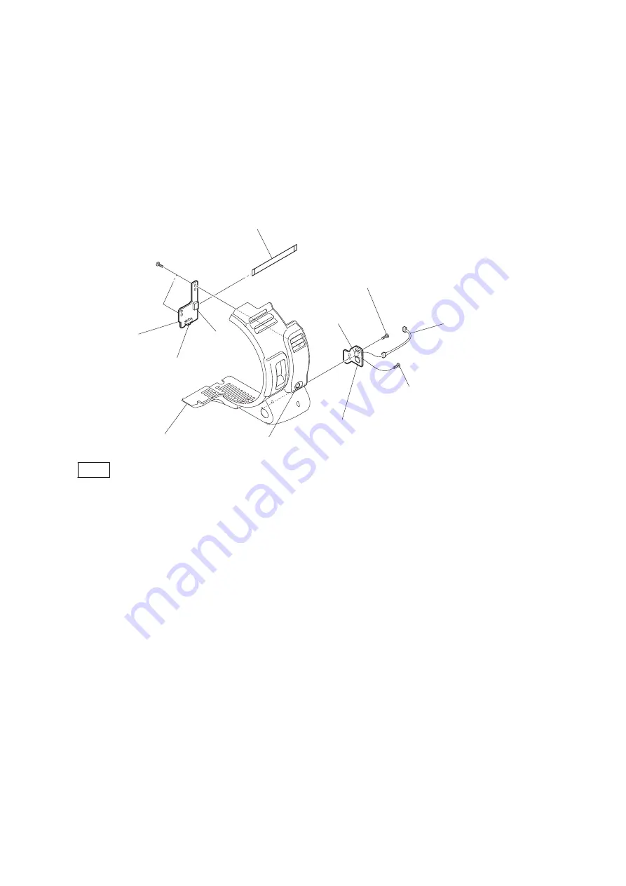
Remove the two screws to detach the SW-1559 board.
2.
Disconnect the harness from the connector CN104 on the SW-1559 board.
3.
Remove the two screws to detach the SW-1573 board.
4.
Disconnect the flexible flat cable from the connector CN100 on the SW-1573 board.
Tapping screws
(2 x 5)
Tapping screw
(2 x 5)
Tapping screw
(2 x 5)
SW-1559 board
Knob
Slide switch
CN100
Front panel assembly
Harness
Flexible flat cable
SW-1573 board
CN104
Note
Align the phase of the slide switch on the SW-1573 board and the knobs on the front panel assembly during
installation.
5.
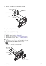
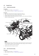
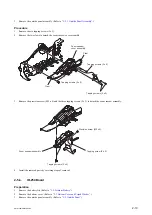
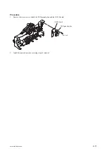
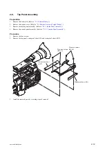
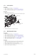
Install the removed parts by reversing steps of removal.
PMW-200/PMW-EX280
2-17
Summary of Contents for PMW-200
Page 1: ...SOLID STATE MEMORY CAMCORDER PMW 200 PMW EX280 SERVICE MANUAL 1st Edition Revised 1 ...
Page 4: ......
Page 8: ......
Page 10: ......
Page 30: ......
Page 38: ...3 Install the removed parts by reversing steps of removal PMW 200 PMW EX280 2 8 ...
Page 82: ......
Page 96: ......
Page 128: ......
Page 130: ......
Page 132: ......
Page 133: ......


